
Gas conveying saturated water removal device

A gas removal technology, applied in the direction of cooling fluid circulation device, combined device, gas treatment, etc., to achieve the effect of automatic operation, convenient movement, and advanced control system

Inactive Publication Date: 2020-11-13
西安科美动力科技有限公司
View PDF0 Cites 0 Cited by
  • Summary
  • Abstract
  • Description
  • Claims
  • Application Information

AI Technical Summary

Problems solved by technology

In the process of gas transportation, due to the requirements of safety and technology, the gas often contains a large amount of free water. When the gas temperature is high (> 40 ℃), the gas contains a large amount of saturated water vapor, and the free water removal device cannot be removed.

Method used


Image

  • Gas conveying saturated water removal device
  • Gas conveying saturated water removal device

Examples


Embodiment Construction

[0023] In order to make the object, technical solution and advantages of the present invention more clear, the present invention will be further described in detail below in conjunction with the accompanying drawings. It should be understood that the specific embodiments described here are only used to explain the present invention, not to limit the present invention.

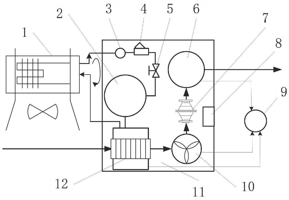
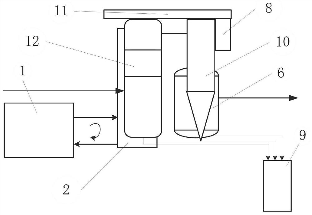
[0024] refer to figure 1 with figure 2 ,

[0025] The gas conveying saturated water removal device includes a cooling circulation pipeline and a dehydration pipeline, and also includes a control cabinet 8 and an endothermic cooler 12. The control cabinet 8 controls the operation of the cooling circulation pipeline and the dehydration pipeline through electrical connections; A chiller 1, a cold water tank 2, a circulating water pump 3, and a Y-type filter can be used for the filter 4; a Y-type filter 4 and a manual gate valve 5; the dehydration pipeline is also provided with a cyclone dehydrator 10, a flame a...


PUM


Abstract

The invention discloses a gas conveying saturated water removal device, which comprises a control cabinet and a heat absorption cooler. The control cabinet controls a cooling circulation pipeline anda dehydration pipeline to operate through electric connection; a water chilling unit, a cold water tank, a circulating water pump, a filter and a manual gate valve are arranged on the cooling circulation pipeline; the dehydration pipeline is also provided with a cyclone dehydrator, a flame arrester and a gas dust remover; the device also comprises an automatic drainer, and the automatic drainer isconnected with the gas dust remover, the cyclone dehydrator and the heat absorption cooler through pipelines. Aiming at the difference of the saturation of water along with the temperature, the waterchilling unit is adopted to absorb gas heat and reduce the gas temperature, and a free water removal device is arranged, so that the dehydration effect is ensured, full-process removal is performed,and the device can be integrally hoisted and is flexible and convenient to move.

Description

technical field [0001] The invention relates to the technical field of gas transmission device design, in particular to a gas transmission saturated water removal device. Background technique [0002] With the country's emphasis on energy and the environment, it has become a trend to use waste gas (gas, biogas, industrial tail gas) to generate electricity, and gas-fired generator sets have been greatly developed. In the process of gas transportation, due to the requirements of safety and technology, the gas often contains a large amount of free water. When the gas temperature is high (>40°C), the gas contains a large amount of saturated water vapor, and the free water removal device cannot be removed. After the gas containing a large amount of saturated water vapor enters the unit, the temperature can rise to about 170°C after being pressurized by the supercharger, and then the mixed gas enters the intercooler and the temperature drops to (35°C-40°C). A large amount of w...

Claims


Application Information

Patent Timeline
Patent Type & Authority Applications(China)
IPC IPC(8): B01D46/00B01D50/00B01D53/26F17D1/02F17D3/14F25D15/00F25D17/02A62C4/02
CPCB01D53/265B01D46/0093F17D1/02F17D3/145F25D15/00F25D17/02A62C4/02B01D2257/80B01D50/20
Inventor 赵亮
Owner 西安科美动力科技有限公司
Learn More