A vulcanization bladder mechanism and its use method

A technology of curing bladder and heating mechanism, applied in the field of tire building, can solve the problems of reducing the contact time between the heat medium and the heating element, the heat medium cannot be fully heated, and the convection effect of the heat medium is poor. Convection effect, effect of reducing vulcanization time

Active Publication Date: 2021-01-12
YONGYI RUBBER CO LTD
View PDF12 Cites 0 Cited by
  • Summary
  • Abstract
  • Description
  • Claims
  • Application Information

AI Technical Summary

Problems solved by technology

However, there are following deficiencies in the above-mentioned technical solution: firstly, the heating element is an open heating coil, and when the heat medium is filled, the heat medium will flow from the gap of the heating element to the surroundings, which reduces the contact time between the heat medium and the heating element , so that the heat medium cannot be fully heated when it is filled; secondly, radial convection is provided through the rotation of the fan blade integrated with the heating element, the rotation mode is single, the convection intensity generated is limited, and the effect of reducing the temperature difference is not ideal
[0005] To sum up, when the vulcanization bladder mechanism in the prior art is vulcanizing and heating the tire, the convection effect of the heat medium in the heating chamber is poor, the temperature difference is large, the heating efficiency is low, the vulcanization time is long, and the production cost is high.

Method used


Image

  • A vulcanization bladder mechanism and its use method
  • A vulcanization bladder mechanism and its use method
  • A vulcanization bladder mechanism and its use method

Examples


specific Embodiment approach

[0067] It should be noted that the structures, proportions, sizes, etc. shown in the drawings attached to this specification are only used to match the content disclosed in the specification, for those who are familiar with this technology to understand and read, and are not used to limit the implementation of the present invention Any modification of structure, change of proportional relationship or adjustment of size shall fall within the range covered by the technical content disclosed in the present invention without affecting the effect and purpose of the present invention. within range.

[0068] At the same time, terms such as "upper", "lower", "left", "right", "middle" and "one" quoted in this specification are only for the convenience of description and are not used to limit this specification. The practicable scope of the invention and the change or adjustment of its relative relationship shall also be regarded as the practicable scope of the present invention without...

Embodiment 1

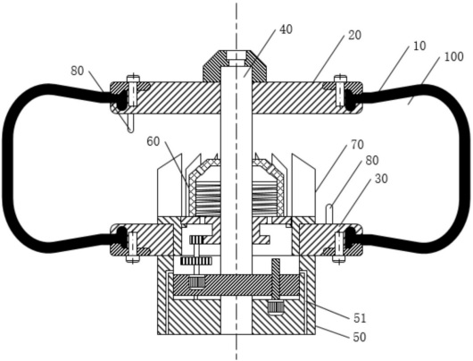
[0070] combined with Figure 1-2 , a vulcanization bladder mechanism, comprising a first heating cavity 100 that can accommodate a heat medium formed jointly by a vulcanization bladder 10, a first fixing plate 20 for fixing the vulcanization bladder 10, and a second fixing plate 30, the first heating A temperature sensor 80 is provided in the cavity 100, the center of the first fixed plate 20 is fixedly connected to the operating shaft 40, the bottom of the second fixed plate 30 is connected to the first housing 50, and the operating shaft 40 slides through the second At the center of the fixed plate 30 and the first housing 50, a heating mechanism 60 can be rotatably arranged above the center of the second fixed plate 30. The heating mechanism 60 is a closed structure, and a heating medium is provided at the bottom. The first through hole 624 has a second through hole 614 connected to the first heating chamber 100 at the top, and a rotatable dispersing mechanism 70 is provide...

Embodiment 2

[0080] In this embodiment, the heater 61 in the first embodiment is optimized and improved so that it can rotate in coordination with the dispersing mechanism 70 to increase the convection velocity of the heat medium. The specific technical scheme is as follows:

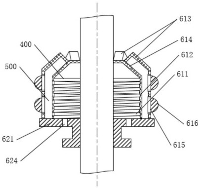
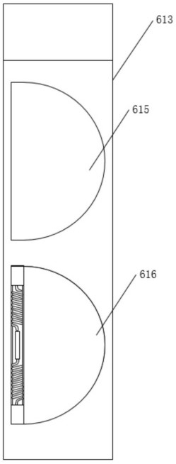
[0081] combined with Figure 3-6 , the heater 61 includes a heating coil 611, a second casing 612 and a sector block 613, the second casing 612 and the sector block 613 are made of heat-conducting materials, and the sector block 613 is fixed on The second housing 612 is provided with a distribution cavity 500 outside and inside, the second through hole 614 communicates with the second heating cavity 400 and the distribution cavity 500, and the outer wall of the sector block 613 is provided with a third The through hole 615, the third through hole 615 is a semicircular through hole and the inside is provided with a turning mechanism 616 that can be turned radially inward or outward by 90° to open the third through ho...


PUM


Abstract

The invention relates to the technical field of tire forming, in particular to a curing bladder mechanism and a using method thereof. The curing bladder mechanism comprises a first heating cavity which is jointly formed by a curing bladder, a first fixing plate and a second fixing plate, wherein the first fixing plate and the second fixing plate are used for fixing the curing bladder, the first heating cavity can contain a heat medium, and a temperature sensor is arranged in the first heating cavity; an operation shaft is fixedly connected to the center of the first fixing plate, a first shellis connected to the bottom of the second fixing plate, and a heating mechanism is rotationally arranged above the center of the second fixing plate and is of a closed structure; a first through holeallowing the heat medium to pass through is formed in the bottom of the heating mechanism, and a second through hole communicating with the first heating cavity is formed in the top of the heating mechanism; and a rotatable dispersing mechanism is further arranged on the periphery of the heating mechanism, and a driving mechanism for driving the heating mechanism and the dispersing mechanism to rotate is arranged in the first shell. The curing bladder mechanism is high in heating efficiency and good in temperature balancing effect, the curing quality is improved, the use amount of the heat medium is reduced, and the production cost is reduced.

Description

technical field [0001] The invention relates to the technical field of tire building, in particular to a vulcanization bladder mechanism and its usage method. Background technique [0002] The tire needs to be vulcanized in the tire vulcanizing machine when it is built. The vulcanizing bladder mechanism is an important part of the tire vulcanizing machine. It is used to load the inner cavity of the green tire to be vulcanized and then pass it into the heat medium. The heat medium can be superheated water or high-temperature steam. Or high-temperature nitrogen and other heat-conducting media, the heat medium expands the vulcanizing bladder, and the expanded vulcanizing bladder is closely attached to the tire to be vulcanized to transfer heat energy, and at the same time cooperate with the vulcanizing mold to perform shaping and vulcanization operations. [0003] In the current vulcanization process, the temperature difference between the upper and lower sides and the front an...

Claims


Application Information

Patent Timeline
Patent Type & Authority Patents(China)
IPC IPC(8): B29D30/06
CPCB29D30/0654B29D30/0662B29D2030/0669B29D2030/0675B29D2030/0677
Inventor 赵会岩刘海军赵海林张学永刘涛
Owner YONGYI RUBBER CO LTD
Why Eureka
Try Eureka