Drilling machine with deflection mechanism and using method thereof

A deflecting mechanism and drilling rig technology, applied in drilling equipment and methods, drilling equipment, directional drilling, etc., can solve the problems of poor stability, complex structure, easy wear at the rotation of the pin shaft, etc., to achieve low friction and improve safety. , The effect of sliding accuracy guarantee

Inactive Publication Date: 2020-11-13
李文美
View PDF1 Cites 6 Cited by
  • Summary
  • Abstract
  • Description
  • Claims
  • Application Information

AI Technical Summary

Problems solved by technology

[0007] Aiming at the above-mentioned shortcomings in the prior art, the present invention provides a drilling rig with a deflection mechanism, which is used to solve the complex structure, poor stability, easy wear and tear of the rotating part of the pin shaft in the prior art, and when the drilling rig only has a drilling rig. When the arm deflection function is disabled, it is impossible to complete drilling operations in complex terrain, etc.

Method used


Image

  • Drilling machine with deflection mechanism and using method thereof
  • Drilling machine with deflection mechanism and using method thereof
  • Drilling machine with deflection mechanism and using method thereof

Examples


Embodiment 1

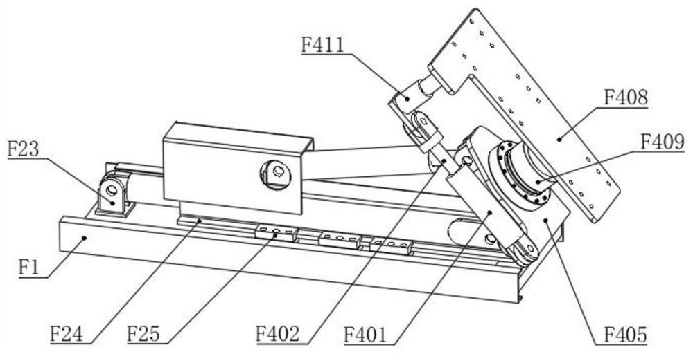
[0076] Such as Figure 1-10 As shown, a drilling rig with a deflection mechanism includes two slider devices A, a double-row chain guide rail device B, a lifting arm device C, a guide sleeve device D, a power head device E and a deflection device F;

[0077] The deflection device F includes a base F1, a first sliding unit F2, an angle adjustment unit F3, a deflection unit F4 and a transport unit F5;

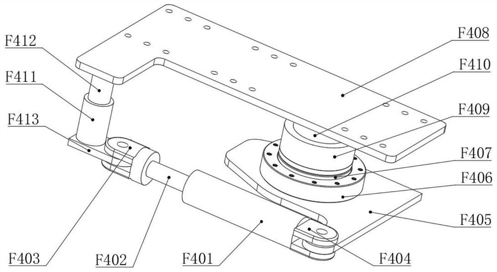
[0078] The deflection unit F4 includes a third hydraulic cylinder F401, a third telescopic rod F402, a swivel seat F405, a bearing seat F406, a slewing support bearing F407 and a drill arm support seat F408. One end of the third telescopic rod F402 is inside the third hydraulic cylinder F401 and connected with it Flexible connection, the swivel seat F405 and the drill arm support seat F408 are both L-shaped flat plates, the outside of the third hydraulic cylinder F401 is movably connected with one end of the swivel seat F405, and the free end of the third telescopic rod F402 is mov...

Embodiment 2

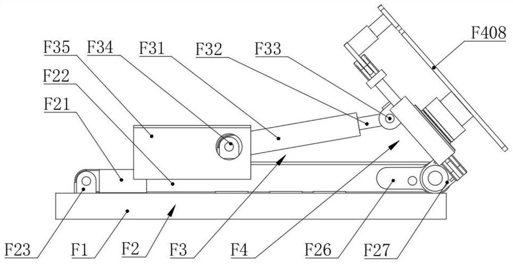
[0093] Such as Figure 1-10 As shown, a drilling rig with a deflection mechanism includes two slider devices A, a double-row chain guide rail device B, a lifting arm device C, a guide sleeve device D, a power head device E and a deflection device F;

[0094] The deflection device F includes a base F1, a first sliding unit F2, an angle adjustment unit F3, a deflection unit F4 and a transport unit F5;

[0095] The first sliding unit F2 is arranged on the upper part of the base F1, the first sliding unit F2 is connected with the lower part of the rotating seat F405, and the first sliding unit F2 and the deflection unit F4 perform synchronous movement;

[0096] The angle adjustment unit F3 is installed on the upper part of the first sliding unit F2, the first sliding unit F2 drives the angle adjustment unit F3 to perform synchronous movement, one end of the angle adjustment unit F3 is connected to the lower part of the rotating seat F405, and the angle adjustment unit F3 drives th...


PUM


Abstract

The invention belongs to the technical field of drilling machines, and particularly relates to a drilling machine with a deflection mechanism and a using method thereof. The drilling machine comprisestwo sliding block devices, a double-row chain guide rail device, a lifting arm device, a guide sleeve device, a power head device and a deflection device; the guide sleeve device and the power head device are each slidably connected with the lifting arm device through one sliding block device; and the guide sleeve device is detachably connected with the power head device, and when the two slidingblock devices slide, the guide sleeve device and the power head device move synchronously. The using method of the drilling machine comprises the following steps of 1, adjusting the deflection device; 2, adjusting the position of a drill arm; 3, carrying out power output of the two sliding block devices; 4, carrying out power transmission of the two sliding block devices; 5, carrying out power output of the power head device; and 6, drilling the guide sleeve device. The drilling machine is convenient to operate, stable and reliable, long in service life, capable of adapting to most construction sites, and high in adaptability of working sites.

Description

technical field [0001] The invention belongs to the technical field of drilling rigs, and in particular relates to a drilling rig with a deflection mechanism and a using method thereof. Background technique [0002] During the drilling process of the drilling rig, it is necessary to drill holes on rocks or concrete. When a round hole needs to be drilled, a cylindrical drill bit is usually used, and the drill bit is provided with end teeth. Drilling rigs need to meet different work needs in different places. In order to adapt to the working environment with slopes, the drill pipe of the drilling rig needs to be deflected at a certain angle to ensure the pass rate of the hole. Driven by the drilling equipment, the drill bit can be The annular groove is drilled on the concrete, and when a certain depth is drilled, the cylindrical main body is pulled out, and the columnar concrete column is pulled out to complete the drilling operation. [0003] In the existing drilling equipme...

Claims


Application Information

Patent Timeline
Patent Type & Authority Applications(China)
IPC IPC(8): E21B7/02E21B7/04E21B15/00E21B15/04
CPCE21B7/02E21B7/04E21B15/003E21B15/045
Inventor 不公告发明人
Owner 李文美
Why Eureka
Try Eureka