A bearing cavity non-contact graphite sealing structure

A sealing structure and graphite sealing technology, applied in the field of bearing cavity sealing, can solve the problems of limited working range of graphite sealing, high frictional power consumption and frictional heat, small size of main sealing surface, etc. The effect of improving the running line speed

Active Publication Date: 2022-03-29
INST OF ENGINEERING THERMOPHYSICS - CHINESE ACAD OF SCI
View PDF0 Cites 0 Cited by
  • Summary
  • Abstract
  • Description
  • Claims
  • Application Information

AI Technical Summary

Problems solved by technology

[0003] First of all, limited by the performance requirements such as the allowable temperature and material hardness of the material, the working range of the graphite seal is limited, and its operating linear speed generally does not exceed 150m / s; secondly, the main sealing surface of the graphite seal is generally small in size. , if it is damaged, it will easily lead to seal failure; again, because the graphite seal is a contact seal, the size of its secondary sealing surface is large, resulting in high frictional power consumption and frictional heat, severe wear, and its service life is generally lower than that of the non-contact seal structure.
[0004] In view of the above-mentioned shortcomings caused by contact, the present invention proposes a non-contact design method for graphite seals, and uses this method to improve the graphite seal structure. The overall structure is relatively simple, and the processing difficulty is the same as that of traditional seal structures, but the seal performance And operating life has been greatly improved, has a wide range of application prospects

Method used


Image

  • A bearing cavity non-contact graphite sealing structure
  • A bearing cavity non-contact graphite sealing structure
  • A bearing cavity non-contact graphite sealing structure

Examples


Embodiment Construction

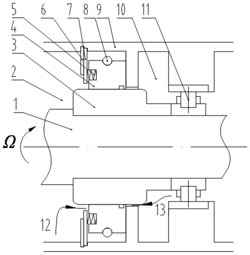
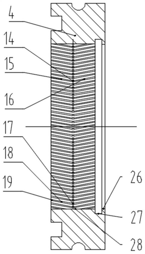
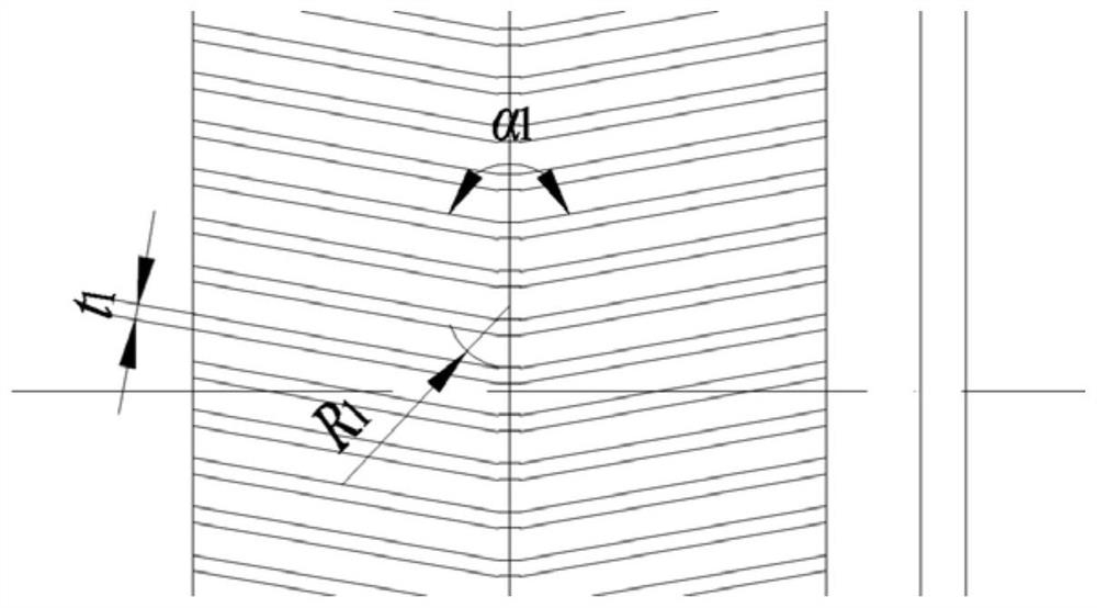
[0032] In order to make the objectives, technical solutions and advantages of the present invention clearer, the technical solutions in the embodiments of the present invention will be described in more detail below in conjunction with the drawings in the embodiments of the present invention. In the drawings, the same or similar reference numerals denote the same or similar elements or elements having the same or similar functions throughout. The described embodiments are some, but not all, embodiments of the invention. The embodiments described below by referring to the figures are exemplary and are intended to explain the present invention and should not be construed as limiting the present invention. Based on the embodiments of the present invention, all other embodiments obtained by persons of ordinary skill in the art without creative efforts fall within the protection scope of the present invention. The structure and technical solutions of the present invention will be ...


PUM


Abstract

The invention discloses a non-contact graphite sealing structure for a bearing cavity, relates to the field of engine bearing cavity sealing, and is particularly suitable for high-efficiency sealing of lubricating oil in the bearing cavity of an aeroengine. Aiming at the shortcomings of the contact graphite seal, such as high frictional power consumption, high frictional heat, and low working line speed, the present invention provides an anti-herringbone dynamic pressure groove on the inner peripheral surface of the graphite sealing ring, and a fishbone type dynamic pressure groove on the outer peripheral surface of the sealed runway. The bone-shaped dynamic pressure groove uses the improved graphite sealing structure of the present invention to reduce the contact area of ​​the rotor and stator, and make the graphite seal tend to be non-contact on the basis of improving the sealing performance, prolong the operating life, and expand the use boundary. The method is simple and clear, easy to implement, and is a very promising sealing structure.

Description

technical field [0001] The invention belongs to the field of sealing of bearing chambers, and relates to a non-contact graphite sealing structure suitable for bearing chambers of aircraft engines and the like. In this structure, an anti-herringbone dynamic pressure groove is set on the inner peripheral surface of the graphite sealing ring pair seal and a herringbone dynamic pressure groove is set on the outer peripheral surface of the sealing track. While improving the sealing performance, by reducing the contact area, Increase the supporting force to make the graphite seal tend to be non-contact, and meet the sealing requirements of modern high-performance aero-engines for lubricating oil in the bearing chamber. Background technique [0002] For modern high-performance aero-engines, in order to pursue higher thrust-to-weight ratio and thermal efficiency, reduce fuel consumption rate, control pollutant emissions and improve working life, it is necessary to continuously break...

Claims


Application Information

Patent Timeline
Patent Type & Authority Patents(China)
IPC IPC(8): F02C7/28F02C7/06
CPCF02C7/28F02C7/06
Inventor 李国庆朱俊强徐纲卢新根张燕峰
Owner INST OF ENGINEERING THERMOPHYSICS - CHINESE ACAD OF SCI
Why Eureka
Try Eureka