An automatic commissioning method and device for transmitting optical power and eye diagram of an optical module
A technology for emitting light and optical eye diagrams, applied in the field of optical modules, can solve problems such as low yield, long working hours, and inability to ensure the best performance of optical module lasers, so as to achieve the best performance and improve production efficiency.
- Summary
- Abstract
- Description
- Claims
- Application Information
AI Technical Summary
Problems solved by technology
Method used
Image
Examples
Embodiment 1
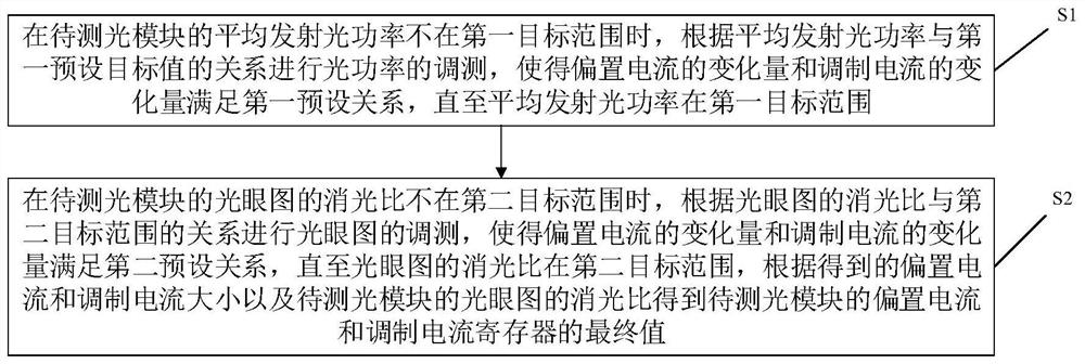
[0038] like figure 1 Shown is a schematic flowchart of a method for automatic adjustment of the emitted optical power and eye diagram of an optical module provided by an embodiment of the present invention. figure 1 The method shown includes the following steps:
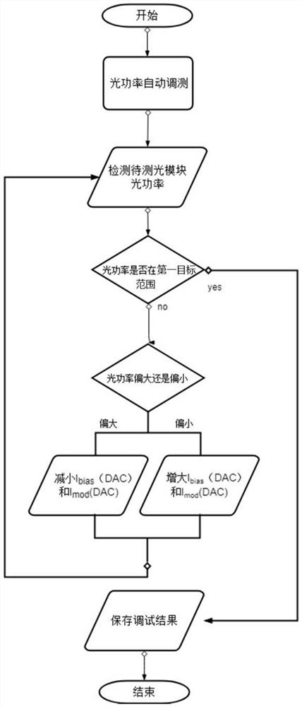
[0039] S1: When the average emitted optical power of the optical module to be measured is not within the first target range, adjust the optical power according to the relationship between the average emitted optical power and the first target range, so that the variation of the bias current and the variation of the modulation current The amount satisfies the first preset relationship until the average emitted optical power is within the first target range;
[0040] In this embodiment of the present invention, the first target range may be determined according to a protocol, standard or specification complied with by the light module to be measured.
[0041] In this embodiment of the present invention, the average e...
Embodiment 2
[0072] like Figure 4 Shown is a schematic structural diagram of an apparatus for automatically adjusting the emitted optical power and eye diagram of an optical module according to an embodiment of the present invention, including:
[0073] The optical power commissioning module 401 is used for commissioning the optical power according to the relationship between the average transmitted optical power and the first target range when the average transmitted optical power of the optical module to be measured is not within the first target range, so that the bias current has a The variation and the variation of the modulation current satisfy the first preset relationship until the average emitted optical power is within the first target range;
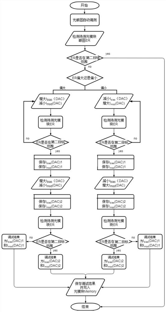
[0074] The eye pattern adjustment module 402 is used for adjusting the optical eye pattern according to the relationship between the extinction ratio of the optical eye pattern and the second target range when the extinction ratio of the ...
Embodiment 3
[0083] Figure 5 It is a schematic structural diagram of an automatic debugging system for optical power and optical eye diagram of an optical module provided by an embodiment of the present invention, which includes: a sampling oscilloscope / eye diagram meter, an optical power meter, and a bit error meter, which are used for testing the optical module. Fixtures, fibers and automatic commissioning devices.
[0084] In actual operation, the operator connects the optical fiber module to be measured, and inserts it into the optical fiber through the test fixture. Figure 5 On the test board shown, the automatic commissioning of the optical power and eye diagram of the transmitting end of the optical module can be realized by the automatic commissioning device.
[0085] The system realizes the real-time debugging of the eye diagram of the module to be measured through the automatic debugging device real-time program-controlled oscilloscope, bit error tester, optical power meter an...
PUM
 Abstract
Description
Claims
Application Information
 - R&D
- Intellectual Property
- Life Sciences
- Materials
- Tech Scout
- Unparalleled Data Quality
- Higher Quality Content
- 60% Fewer Hallucinations
Browse by: Latest US Patents, China's latest patents, Technical Efficacy Thesaurus, Application Domain, Technology Topic, Popular Technical Reports.
© 2025 PatSnap. All rights reserved.Legal|Privacy policy|Modern Slavery Act Transparency Statement|Sitemap|About US| Contact US: help@patsnap.com


