
Automatic debugging and testing method and device for transmitting optical power and eye pattern of optical module

A technology of emitting light and optical eye diagram, applied in the field of optical modules, it can solve the problems of low yield, long working hours and increase, and achieve the effect of meeting automation requirements, best performance and improving production efficiency

Active Publication Date: 2020-11-13
YANGTZE OPTICAL FIBRE & CABLE CO LTD
View PDF11 Cites 4 Cited by
  • Summary
  • Abstract
  • Description
  • Claims
  • Application Information

AI Technical Summary

Problems solved by technology

The traditional commissioning method is to count the batch data and preset fixed parameters, which cannot meet the needs of different batches. Therefore, the traditional commissioning method cannot well ensure that the optical module can play the best performance of the laser.
[0004] Distributed feedback laser (Distributed-feedback laser, DFB) is currently the most commonly used laser type for 1.25G to 25G optical modules. In order to save costs, many manufacturers no longer use backlight diodes in the production process of Transistor Outline (TO). , which leads to the inability of the optical module to monitor the transmitted optical power, so that the laser must work in an open-loop state, and the automatic power control (Automatic Power Control, APC) function is no longer applicable. difficulty
Traditional commissioning methods are divided into manual commissioning and preset fixed parameters. Manual commissioning is also based on preset fixed parameters, which can maximize the best performance of devices, but requires long hours of work and depends on The technicality and proficiency of the operator and the defects of low efficiency, the commissioning method with preset fixed parameters is strongly dependent on the batch consistency, it is not easy to exert the best performance of the device, and has the defect of low yield

Method used


Image

  • Automatic debugging and testing method and device for transmitting optical power and eye pattern of optical module
  • Automatic debugging and testing method and device for transmitting optical power and eye pattern of optical module
  • Automatic debugging and testing method and device for transmitting optical power and eye pattern of optical module

Examples


Embodiment 1

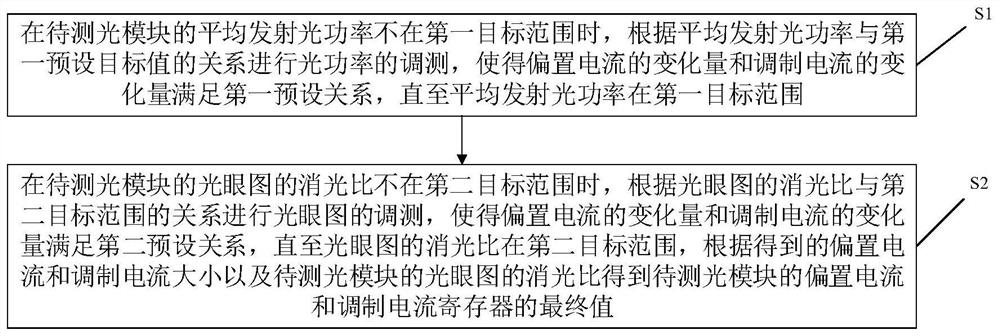
[0038] Such as figure 1 Shown is a schematic flow chart of an automatic commissioning method for transmitting optical power and eye diagram of an optical module provided by an embodiment of the present invention. figure 1 The method shown includes the following steps:

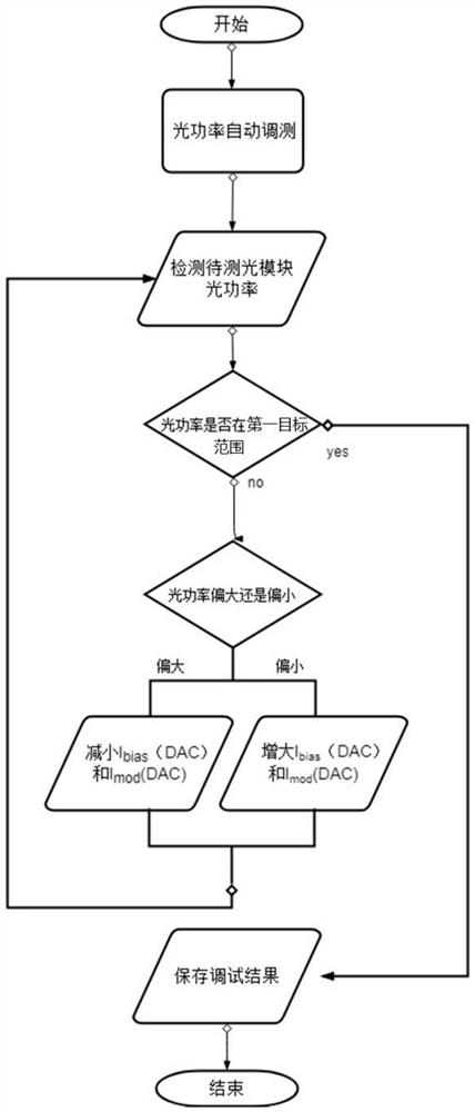
[0039] S1: When the average transmitted optical power of the optical module to be tested is not within the first target range, perform optical power commissioning according to the relationship between the average transmitted optical power and the first target range, so that the variation of the bias current and the change of the modulation current The amount satisfies the first preset relationship until the average emitted optical power is within the first target range;

[0040] In the embodiment of the present invention, the first target range may be determined according to the protocol, standard or specification followed by the optical module to be tested.

[0041] In the embodiment of the present invention...

Embodiment 2

[0072] Such as Figure 4 Shown is a schematic structural diagram of an automatic commissioning device for transmitting optical power and eye diagrams of an optical module provided by an embodiment of the present invention, including:

[0073] The optical power commissioning module 401 is configured to perform commissioning of the optical power according to the relationship between the average transmitted optical power and the first target range when the average transmitted optical power of the optical module to be tested is not within the first target range, so that the bias current The amount of variation and the amount of variation of the modulation current satisfy a first preset relationship until the average emitted optical power is within the first target range;

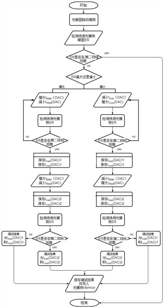
[0074] The eye diagram commissioning module 402 is configured to perform commissioning of the optical eye diagram according to the relationship between the extinction ratio of the optical eye diagram and the sec...

Embodiment 3

[0083] Figure 5 It is a schematic structural diagram of an automatic commissioning system for optical module optical power and optical eye diagram provided by an embodiment of the present invention, which includes: a sampling oscilloscope / eye diagram instrument, an optical power meter, and a bit error meter for testing the optical module Fixtures, fiber optics and automatic commissioning devices.

[0084] In actual operation, the operator connects the optical module to be tested to the optical fiber, and inserts it into the Figure 5 On the test board shown, the automatic commissioning device can realize the automatic commissioning of the optical power and eye diagram of the transmitting end of the optical module.

[0085] The system realizes the real-time commissioning of the eye diagram of the module to be tested through the real-time program-controlled oscilloscope, bit error detector, optical power meter and optical module to be tested through the automatic commissioning...


PUM


Abstract

The invention discloses an automatic debugging and testing method and device for transmitting optical power and an eye pattern of an optical module and belongs to the field of optical modules. The method comprises the steps that when the average emission light power is not in a first target range, debugging and testing of the light power are carried out according to the relation between the average emission light power and the first target range, and therefore the variation of a bias current and the variation of a modulation current meet a first preset relation until the average emission lightpower is in the first target range; when the extinction ratio of the light eye pattern is not in the second target range, the optical eye pattern is debugged and tested according to the relationshipbetween the extinction ratio and the second target range, the variation of the bias current and the variation of the modulation current are enabled to meet a second preset relation until the extinction ratio is within a second target range, and the final values of the bias current and the modulation current of the to-be-tested optical module are obtained according to the magnitude of the obtainedbias current and modulation current and the extinction ratio. According to the method disclosed in the invention, optical power and extinction ratio parameters can be quickly adjusted to the target range without manual intervention.

Description

technical field [0001] The invention belongs to the field of optical modules, and more particularly relates to an automatic commissioning method and device for transmitting optical power and an eye pattern of an optical module. Background technique [0002] With the layout and construction of the global network and the gradual advancement of the 5G network, the demand for optical modules in the international and domestic markets continues to increase, and the competition in the optical module industry is becoming increasingly fierce. Winning the competition has become the direction that all parties have been striving for. [0003] Optical module automatic testing is one of the important links in optical module manufacturing. Due to the poor consistency of optical module lasers, it is impossible to make the module performance meet the requirements through preset fixed parameters during mass production. It is often necessary to adjust the parameters. With the continuous incre...

Claims


Application Information

Patent Timeline
Patent Type & Authority Applications(China)
IPC IPC(8): H04B10/079H04B10/564
CPCH04B10/07955H04B10/0795H04B10/564
Inventor 瞿子敬薄生伟鲁振华
Owner YANGTZE OPTICAL FIBRE & CABLE CO LTD
Learn More