
Small atomizer for treating respiratory diseases

A nebulizer and respiratory tract technology, applied in the field of small nebulizers, can solve problems such as inability to continue treatment

Active Publication Date: 2020-11-17
安徽康居人健康科技有限公司
View PDF12 Cites 0 Cited by
  • Summary
  • Abstract
  • Description
  • Claims
  • Application Information

AI Technical Summary

Problems solved by technology

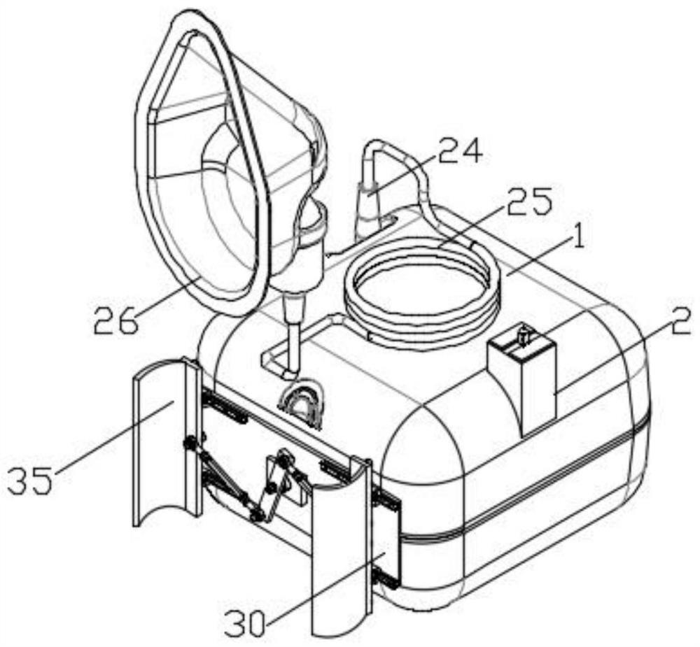
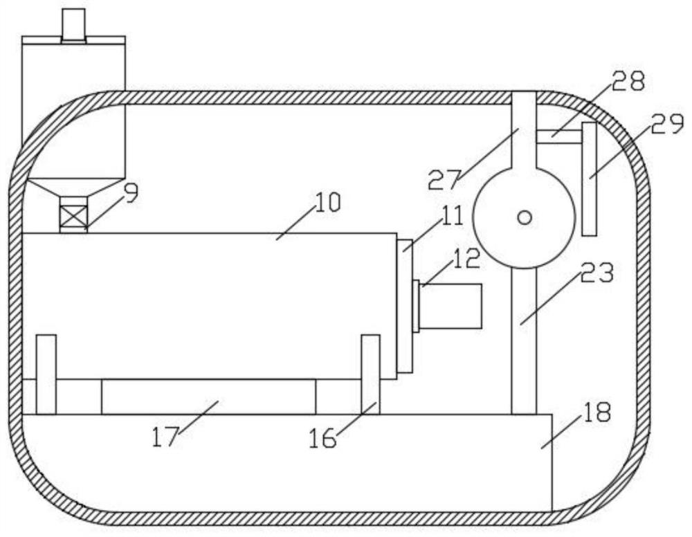
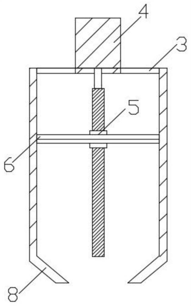
[0004] The object of the present invention is to provide a small atomizer for treating respiratory diseases, which solves the following technical problems: (1) by placing the child's waist between two arc-shaped waist clips, the rotating cylinder drives the rotating bar to rotate, and the rotating bar rotates The bar pulls the two centering plates to move towards each other through two rotating pull rods, and the two centering plates drive two arc-shaped waist clips to clamp the children's waist. Through the above structure, this small atomizer is convenient for children with respiratory diseases. Children are treated, and the children's waist is clamped by the curved waist clips on both sides, so as to avoid the situation that the children cannot continue the treatment due to the children's disturbance during the treatment process; The liquid inlet on the top is poured into the liquid inlet pipe, the first motor cooperates with the ball screw to drive the filter frame up and down, and the scrapers on the four sides of the filter frame scrape off the remaining liquid medicine on the inner wall of the liquid inlet pipe. The filter screen on the frame absorbs the dust entering from the liquid inlet, and the repeated lifting and moving process of the filter screen frame prevents the filter screen from being blocked. The motor drives the central gear to rotate, and the meshing of the central gear drives the three planetary gears to rotate. The three planetary gears coaxially drive the three agitating rollers to rotate. The three agitating rollers stir and mix the liquid medicine in the mixing chamber. The liquid pipe enters the heating chamber, and the electric heating pipe heats the medicinal liquid entering the heating chamber. The ultrasonic generator drives the ultrasonic vibrating head to vibrate in the heating chamber. The atomizing tube and atomizing bucket extract the water droplets vibrating out of the liquid surface to the connecting pipe, and transport it to the connecting hose through the connecting pipe, and finally spray the atomized liquid into the breathing mask, and absorb the atomized drug through the breathing mask Liquid, by setting two liquid inlets on the liquid inlet pipe, it is convenient to add different liquid medicines at the same time, and through the design of the filter frame that can be lifted and lowered repeatedly, it can ensure that the filter frame is always in a dynamic environment and prevent the filter frame from being filtered. The dust adsorbed on the net blocks the column filter and affects the delivery of the liquid medicine. The design of the scraper on the filter frame scrapes off the liquid medicine remaining on the inner wall of the liquid inlet pipe to prevent the waste of the liquid medicine. With the cooperation of two planetary gears, the three stirring rollers stir the liquid medicine, with high stirring efficiency and high degree of mixing of the liquid medicine; (3) When the connecting hose is blocked, the atomized medicine liquid delivered by the blower stays in the connecting pipe and communicates When the pressure inside the tube increases, the connecting pipe presses toward the pressure sensor through the pressure outlet pipe, and the blower is turned off to prevent the connecting pipe from bursting. When the connecting hose is blocked, the small atomizer will turn off the blower in time to prevent the connecting pipe from bursting. have a certain degree of security

Method used


Image

  • Small atomizer for treating respiratory diseases
  • Small atomizer for treating respiratory diseases
  • Small atomizer for treating respiratory diseases

Examples


Embodiment Construction

[0033] The following will clearly and completely describe the technical solutions in the embodiments of the present invention with reference to the accompanying drawings in the embodiments of the present invention. Obviously, the described embodiments are only some, not all, embodiments of the present invention. Based on the embodiments of the present invention, all other embodiments obtained by persons of ordinary skill in the art without creative efforts fall within the protection scope of the present invention.

[0034] see Figure 1-8 As shown, the present invention is a small nebulizer for treating respiratory diseases, including a main housing 1, a liquid inlet tube 2 is installed on the top side of the main housing 1, and a drainage tube 8 is installed at the bottom of the liquid inlet tube 2. A connecting pipe 9 is installed at the bottom of the drainage tube 8, and the bottom of the connecting pipe 9 communicates with the mixed liquid chamber 10. The inner cavity of t...


PUM


Abstract

The invention discloses a small atomizer for treating respiratory diseases. The small atomizer is convenient for treating children with respiratory diseases, and clamps the waist of the children through arc waist clamps on two sides to prevent the condition of incapability of continuously treating caused by movement of the children in the treatment process of the children; two liquid inlets are formed in a liquid inlet pipe for conveniently adding different liquid medicines at the same time; through a filter screen frame design capable of repeatedly lifting, the filter screen frame is always in a dynamic environment to prevent blockage of a column filter screen by dust absorbed on the filter screen frame to influence conveying of the liquid medicines; through a scraper on the filter screenframe, the liquid medicines remained on the inner wall of the liquid inlet pipe are scraped to prevent the condition of waste of the remained liquid medicines; and through cooperation between a center tooth and three planet teeth, three stirring rollers stir the liquid medicines, so that the stirring efficiency is high, and the mixing degree of the liquid medicines is high.

Description

technical field [0001] The invention relates to the technical field of nebulizer production, in particular to a small nebulizer for treating respiratory diseases. Background technique [0002] Due to immature physical development, children have low immunity; at the same time, due to the poor air quality in recent years, a large range of children's respiratory diseases often appear at the turn of seasons. In the treatment of pediatric respiratory diseases, medical nebulizers are an important therapeutic equipment. [0003] The patent document (CN201810782891.9) discloses a nebulizer for pediatric respiratory treatment. The nebulizer adds the respiratory spray liquid into the measuring liquid cylinder 22 and introduces it into the box 2 through the bottom drainage tube 23. In the liquid tank 7, the opening and closing of the electromagnetic valve 24 on the drainage tube 23 is controlled in real time by the float level switch 10, which is convenient for controlling the amount ...

Claims


Application Information

Patent Timeline
IPC IPC(8): A61M11/00
CPCA61M11/00
Inventor 郭本胜梁锐
Owner 安徽康居人健康科技有限公司
Learn More