Bathroom pipeline joint forming finish machining treatment process

A technology for pipe joints and processing technology, which is applied in metal processing equipment, manufacturing tools, grinding workpiece supports, etc., and can solve problems affecting the quality of pipe joints, affecting anti-corrosion effects, rusting and corrosion of pipes, etc.

Inactive Publication Date: 2020-11-17
谢祥松
View PDF10 Cites 2 Cited by
  • Summary
  • Abstract
  • Description
  • Claims
  • Application Information

AI Technical Summary

Problems solved by technology

The bathroom joint is a part used to connect water pipes. As we all know, most of the shower pipes in the shower room are manufactured by casting. The work needs to do a good job in the anti-corrosion and anti-rust work of the pipeline to avoid the problem that the pipeline will be rusted and corroded due to the long-term use of the pipeline, which will cause harm to human health.
[0003] In the molding process of bathroom pipeline joints, according to the molding processing method, the molding finishing treatment equipment used in the existing finishing treatment process has the following defects: 1. The existing molding finishing treatment equipment is not clamping the pipeline joints. The pipe joints cannot be clamped stably during the process, resulting in the instability of the pipe joints during polishing, which affects the quality of the pipe joints, and the residue inside the pipe joints cannot be cleaned, resulting in that the pipe joints cannot be maintained during spraying. The clean and tidy state affects the anti-corrosion effect of spraying; 2. When the existing forming and finishing equipment is profiled on the pipeline joints, it cannot timely clean up the residue rust on the profiled surface, resulting in the surface of the pipeline joints being damaged due to excessive temperature High, the burrs still adhere to the surface of the pipe joint

Method used


Image

  • Bathroom pipeline joint forming finish machining treatment process
  • Bathroom pipeline joint forming finish machining treatment process
  • Bathroom pipeline joint forming finish machining treatment process

Examples


Embodiment Construction

[0034]The specific embodiment of the present invention will be described in further detail by describing the embodiments below with reference to the accompanying drawings, the purpose is to help those skilled in the art to have a more complete, accurate and in-depth understanding of the concept and technical solutions of the present invention, and To facilitate its practice, but not as a limitation of the invention.

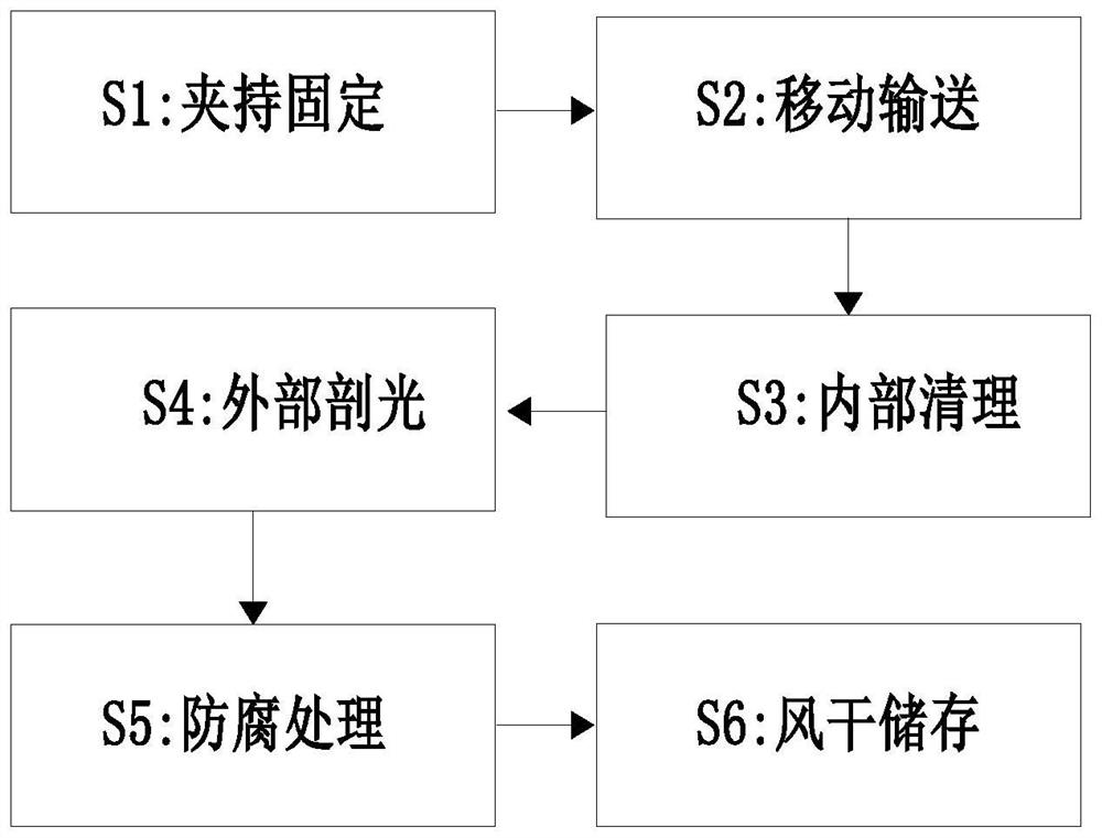
[0035] See attached Figure 1-8 As shown, a bathroom pipeline joint molding finishing treatment process, the bathroom pipeline joint molding finishing treatment process specifically includes the following steps:

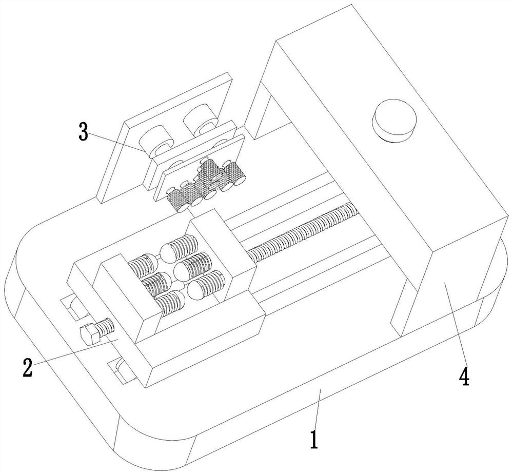
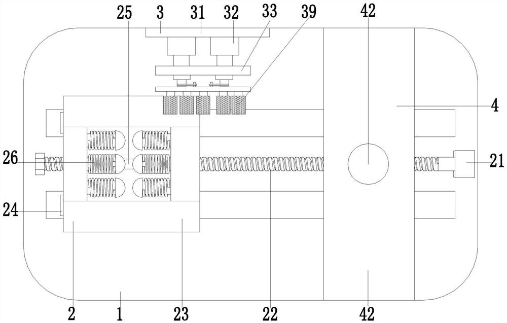
[0036] S1. Clamping and fixing: manually place the pipeline joint to be processed on the fixture table 23, and clamp and fix it by the clamping mechanism 26;

[0037] S2. Mobile transportation: through the mutual cooperation of the rotating motor 21 and the lead screw 22, the fixture table 23 is transported to the light cutting mechanism 39;

[0038] ...


PUM


Abstract

The invention relates to a bathroom pipeline joint forming finish machining treatment process, in particular to bathroom pipeline joint forming finish machining treatment equipment. The equipment comprises a bottom plate, a movable clamping device, a polishing device and an anti-corrosion device, a sliding groove is formed in the middle of the bottom plate, and the movable clamping device is installed on the bottom plate in a sliding fit manner. The polishing device is installed in the middle of the bottom plate, and the anti-corrosion device is installed at the right side of the bottom plateand located on the right side of the polishing device. The equipment can solve the problems that when an existing device clamps a pipeline joint, the pipeline joint cannot be stably clamped, consequently, the pipeline joint is unstable during polishing, the polishing quality of the pipeline joint is affected, residues in the pipeline joint cannot be cleaned up, the spraying anti-corrosion effect is affected, residual rust on the polished surface cannot be cleaned up in time, and burrs are still adhered to the surface of the pipeline joint due to over-high temperature of the surface of the pipeline joint.

Description

technical field [0001] The invention relates to the technical field of finish machining of bathroom pipeline joints, and specifically proposes a molding and finishing treatment process for bathroom pipeline joints. Background technique [0002] Pipe joints have the functions of convenient installation, superior performance, and long service life, and are widely used in the construction of water supply and drainage projects in the fields of water supply, drainage, electric power, metallurgy, urban construction, petroleum, chemical and environmental protection, and large and medium-sized enterprises. The bathroom joint is a part used to connect water pipes. As we all know, most of the shower pipes in the shower room are manufactured by casting. The work needs to do a good job in the anti-corrosion and anti-rust work of the pipeline to avoid the problem that the pipeline will be rusted and corroded due to the long-term use of the pipeline, which will cause harm to human health....

Claims


Application Information

Patent Timeline
Patent Type & Authority Applications(China)
IPC IPC(8): B24B9/04B24B27/033B24B41/06B24B41/04B24B41/02B24B47/14B24B47/04B24B55/06B08B9/047B05B9/04
CPCB05B9/0413B08B9/0436B08B9/047B24B9/04B24B27/033B24B41/02B24B41/04B24B41/06B24B47/04B24B47/14B24B55/06
Inventor 谢祥松
Owner 谢祥松
Why Eureka
Try Eureka