Stacking equipment for cast plunger pumps

A plunger pump and equipment technology, applied in the field of plunger pump stacking equipment after casting, can solve the problems of plunger pump falling off, slow plunger pump, plunger pump damage, etc., and achieve the effect of avoiding falling off and avoiding extrusion force

Active Publication Date: 2020-11-17
JIANGXI HYDRAULIC PIECES
View PDF9 Cites 1 Cited by
  • Summary
  • Abstract
  • Description
  • Claims
  • Application Information

AI Technical Summary

Problems solved by technology

[0004] The invention provides a post-casting stacking equipment for plunger pumps. The purpose is to solve the following problems in the current manual stacking of plunger pumps: (1) The surface shape of the plunger pump is irregular, and the plunger pump cannot be stacked by hand. Stable clamping may easily cause the plunger pump to fall off, resulting in collision between the plunger pump and the inside of the stor

Method used


Image

  • Stacking equipment for cast plunger pumps
  • Stacking equipment for cast plunger pumps
  • Stacking equipment for cast plunger pumps

Examples


Example Embodiment

[0028] The embodiments of the present invention are described in detail below with reference to the accompanying drawings, but the present invention can be implemented in many different ways as defined and covered by the claims.

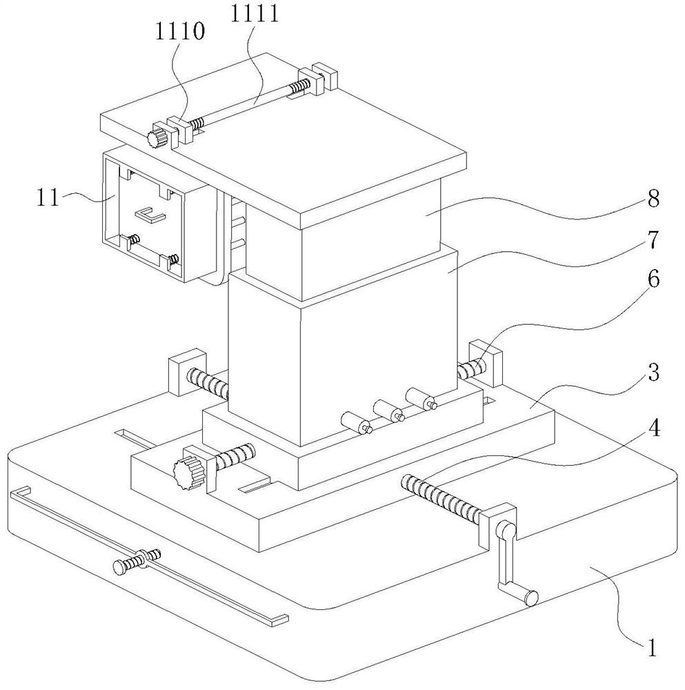
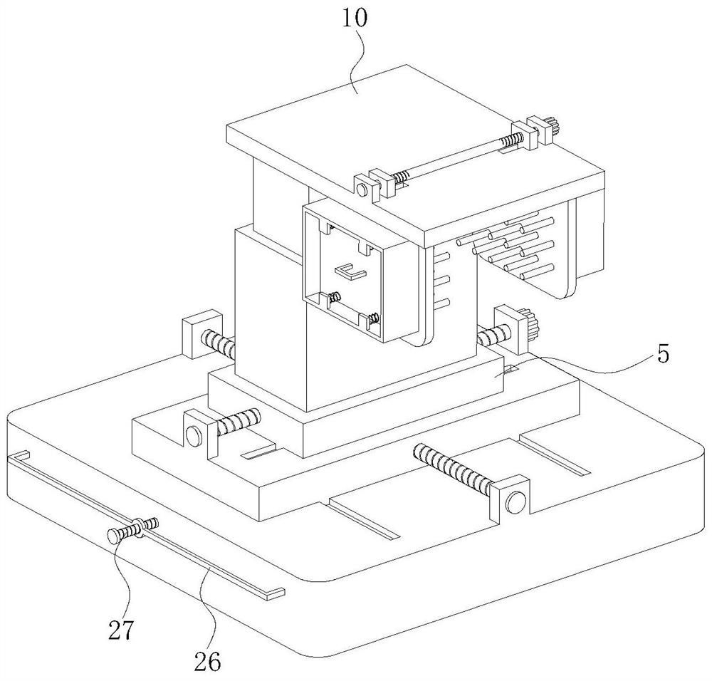
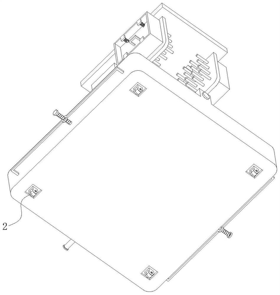
[0029] like Figure 1 to Figure 6 As shown, this embodiment provides a plunger pump stacking equipment after casting, including a base 1 with a rectangular cross-section, a lifting mechanism 2 is installed on the lower surface of the base 1, and a horizontal first A sliding plate 3. A first lead screw 4 arranged in the front-rear direction and horizontally penetrating the first sliding plate 3 is rotatably installed on the upper surface of the base 1 through a bracket, and a rotating handle is fixedly installed at the end of the first lead screw 4 . The upper surface of the first sliding plate 3 is slidably fitted with a horizontal second sliding plate 5 along the left-right direction. The upper surface of the first sliding plate 3 is rotated and in...


PUM


Abstract

The invention belongs to the technical field of plunger pump manufacturing, and particularly relates to stacking equipment for cast plunger pumps. The stacking equipment comprises a base, wherein lifting mechanisms are installed on the lower surface of the base, a first sliding plate is arranged on the base in a sliding fit mode, a second sliding plate is in sliding fit with the first sliding plate, a limiting sleeve is vertically and fixedly installed on the upper surface of the second sliding plate, a supporting column is vertically in sliding fit with the interior of the second sliding plate, a buffer mechanism is mounted in the limiting sleeve, a horizontal top plate is fixedly mounted at the top of the supporting column; and a clamping mechanism is mounted on the top plate. Accordingto the stacking equipment, in the process of clamping the plunger pump through a clamping mechanism, a supporting rod can freely stretch out and draw back in a sealing barrel according to the shape ofthe surface of the plunger pump, so that the irregular surface of the plunger pump is supported, and stable clamping of the plunger pump is achieved; and the plunger pump can slowly descend through the buffer mechanism, so that the position of the plunger pump can be finely adjusted, and a plunger pump shell is fully matched with the inner wall of a storage box.

Description

technical field [0001] The invention belongs to the technical field of plunger pump manufacturing, and in particular relates to a stacking equipment for a plunger pump after casting. Background technique [0002] The plunger pump is an important device of the hydraulic system. It relies on the reciprocating movement of the plunger in the cylinder to change the volume of the sealed working chamber to achieve oil suction and pressure. The plunger pump has the advantages of high rated pressure, compact structure, high efficiency and convenient flow adjustment, so it is widely used in high pressure, large flow and flow adjustment occasions, such as hydraulic presses, engineering machinery and ships. The plunger pump is usually molded by casting. After casting, in order to facilitate storage and transportation of the plunger pump, it is necessary to put the plunger pump into a storage box that cooperates with its shell. At present, the process of stacking the plunger pump is don...

Claims


Application Information

Patent Timeline
IPC IPC(8): B65G61/00
CPCB65G61/00
Inventor 周海林杨华束立新
Owner JIANGXI HYDRAULIC PIECES
Why Eureka
Try Eureka