
Two-stage gas producer for glass production

A gas generator and two-stage technology, which is applied in the gasification process, the manufacture of combustible gas, and the feeding tool of the gasification device, etc., can solve the problems of reducing the gas production efficiency, affecting the gas production efficiency, and insufficient reaction. The effect of reducing the size difference

Active Publication Date: 2020-11-17
台州市路桥友顺纸塑包装材料厂
View PDF18 Cites 0 Cited by
  • Summary
  • Abstract
  • Description
  • Claims
  • Application Information

AI Technical Summary

Problems solved by technology

[0004] Most of the existing two-stage gasifiers are in the shape of horns in the process of cutting materials, in order to make the coal falling on the horns evenly dispersed as much as possible, but in the actual use process, it is affected by coal Due to the influence of the gravity of the material itself, the coal ash flows down along the side wall of the unloading device, which makes the coal material uneven when it is distributed, which greatly affects the efficiency of gas production
[0005] At the same time, most of the existing feeding devices can only arrange the coal materials evenly, but in the actual use process, due to the different sizes of the coal materials, the coal materials of different sizes will be different in the process of distributing the coal materials. At the same time, the smaller size coal materials will react first, and the larger size coal materials will slow down the reaction, which will cause some larger size coal materials to react after the coal materials are distributed. Insufficient phenomenon
[0006] Moreover, in the process of distributing the existing coal materials, most of the coal materials are initially preheated by the heat of the reaction furnace itself, so that during the distributing process of the coal materials, the larger coal materials will be preheated. The phenomenon of thermal incompleteness, which greatly reduces the efficiency of gas production

Method used


Image

  • Two-stage gas producer for glass production
  • Two-stage gas producer for glass production
  • Two-stage gas producer for glass production

Examples


Embodiment Construction

[0026] The following will clearly and completely describe the technical solutions in the embodiments of the present invention with reference to the accompanying drawings in the embodiments of the present invention. Obviously, the described embodiments are only some, not all, embodiments of the present invention. Based on the embodiments of the present invention, all other embodiments obtained by persons of ordinary skill in the art without making creative efforts belong to the protection scope of the present invention.

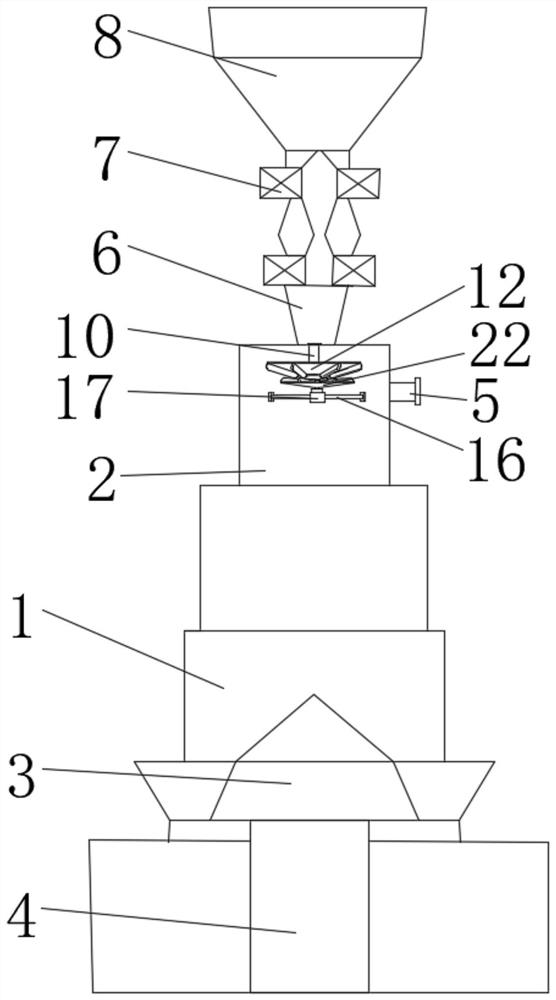
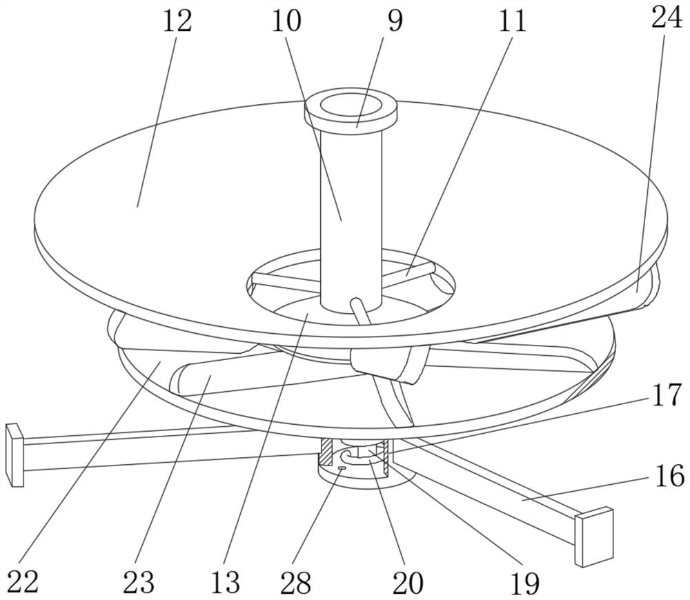
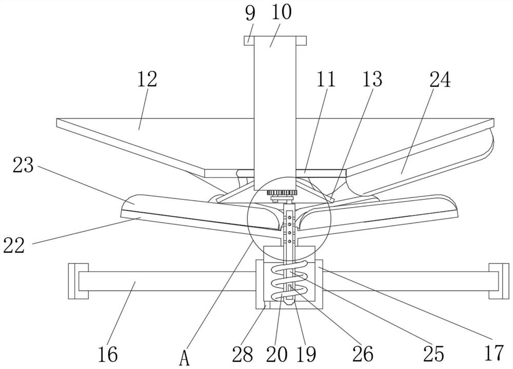
[0027] see Figure 1-6, a two-stage gas generator for glass production, comprising a furnace body 1, the upper end of the furnace body 1 is provided with a reaction chamber 2, and the bottom end of the inner wall of the furnace body 1 is fixedly equipped with an ash row 3, and the bottom end of the furnace body 1 The middle part is provided with the inlet pipe 4 communicating with the ash row 3, the side wall of the furnace body 1 is fixedly installed with the...


PUM


Abstract

The invention relates to the related technical field of glass manufacturing, and discloses a two-stage gas producer for glass production. The two-stage gas producer comprises a producer body, whereinthe upper end of the producer body is provided with a reaction cavity, the bottom end of the inner wall of the producer body is fixedly provided with an ash discharging device, the middle part of thebottom end of the producer body is provided with a gas inlet pipe communicating with the ash discharging device, a gas outlet pipe communicating with the reaction cavity is fixedly mounted on the sidewall of the producer body, and a coal inlet pipe is fixedly mounted at the top end of the producer body. By arranging a supporting rod and a fixing rod which are different in taper and due to the fact that the taper of a first-stage material distributing plate is smaller than the taper of the second-stage material distributing plate, when coal materials fall onto the surface of the first-stage material distributing plate, the coal materials with light weight are thrown out through the first-stage material distributing plate firstly, and the coal materials with large sizes roll down to the second-stage material distributing plate due to large self gravity and are thus thrown out from the surface of the second-stage material distributing plate with a gentle slope, so material distribution is carried out through the self gravity of the coal materials; and thus, hierarchy and uniformity of the material distribution are realized, and finally, the purpose of uniform material distribution isachieved.

Description

technical field [0001] The invention relates to the technical field related to glass manufacturing, in particular to a two-stage gas generator for glass production. Background technique [0002] The two-stage gas generator is an equipment that provides the mixed gas generator gas required for the production of machinery, building materials and light industries. With the daily development of technology and the rapid advancement of science and technology, the technology of the two-stage cold gas generator used in it The requirements are getting higher and higher, [0003] The working principle of the existing two-stage gasifier is as follows: first, the coal enters the furnace body from the top coal bunker through two sets of lower coal valves, and the coal undergoes sufficient drying and long-term low-temperature dry distillation in the dry distillation section to gradually form semi-coke. Entering the gasification section, the hot semi-coke fully reacts with the gasifying a...

Claims


Application Information

Patent Timeline
Patent Type & Authority Applications(China)
IPC IPC(8): C10J3/60
CPCC10J3/60C10J2200/15C10J2300/0906
Inventor 施吉章
Owner 台州市路桥友顺纸塑包装材料厂
Learn More