Special-shaped cable bent tower decorative plate mounting device and construction method

A technology for installing devices and decorative panels, which is applied in the direction of erecting/assembling bridges, bridge parts, bridges, etc., which can solve the problems of labor-consuming and time-consuming erection and dismantling of operating platforms, large differences in the length and size of decorative panels, and unfavorable access for personnel on operating platforms. Achieve the effects of positioning and welding work, reducing engineering costs, and simple structure

Active Publication Date: 2020-11-17
CCCC SECOND HARBOR ENG +1
View PDF14 Cites 2 Cited by
  • Summary
  • Abstract
  • Description
  • Claims
  • Application Information

AI Technical Summary

Problems solved by technology

The conventional installation method has the following deficiencies: (1) When the number of external decorative panels is installed too much, it takes a lot of time to set up and dismantle the operation platform, and it is not easy to repair the embedded parts; (2) When the operation platform and the decorative panels are hoisted separately, it will occupy Excessive lifting equipment, limited space, and the intersection of decorative panels and steel wire rope slings on the platform pose safety risks; (3) When the cross-section of the tower column changes gradually, the length and size of the decorative panels vary greatly, and the adaptability of a single-sized operating platform is poor. It takes man-hours and materials to adapt the size of the platform; (4) The size and flexibility of the decorative board itself is relatively large, in order to avoid hoisting deformation, special lifting tools need to be processed; (5) The separation of the upper and lower working platforms is not conducive to the passage of personnel and cannot Ensure the safety of workers

Method used


Image

  • Special-shaped cable bent tower decorative plate mounting device and construction method
  • Special-shaped cable bent tower decorative plate mounting device and construction method
  • Special-shaped cable bent tower decorative plate mounting device and construction method

Examples


Embodiment Construction

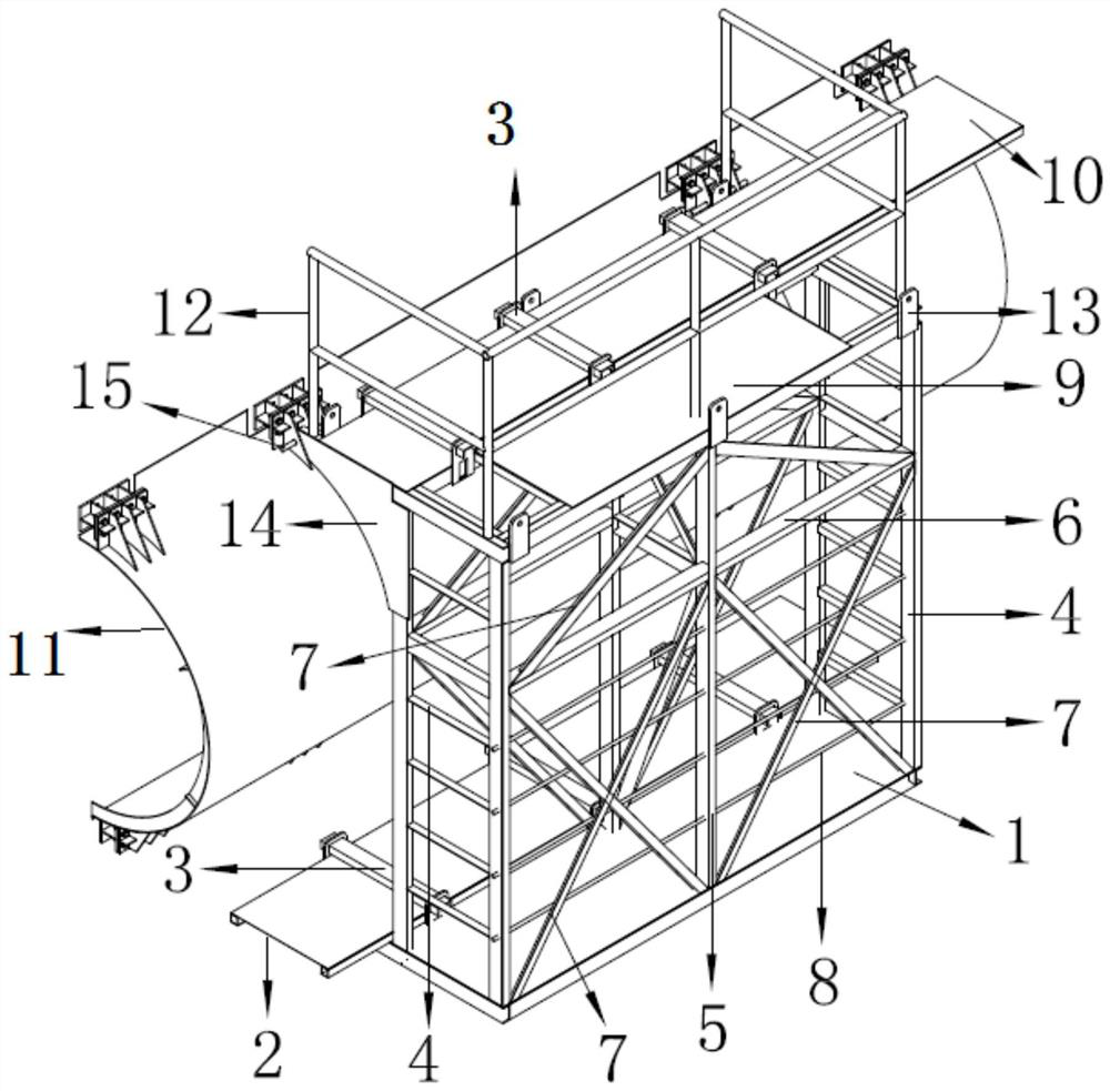
[0041] The present invention will be further described in detail below in conjunction with the accompanying drawings, so that those skilled in the art can implement it with reference to the description.

[0042] It should be noted that the experimental methods described in the following embodiments, unless otherwise specified, are conventional methods, and the reagents and materials, if not otherwise specified, can be obtained from commercial sources; in the description of the present invention, The terms "landscape", "portrait", "top", "bottom", "front", "rear", "left", "right", "vertical", "horizontal", "top", "bottom", The orientation or positional relationship indicated by "inner", "outer", etc. is based on the orientation or positional relationship shown in the drawings, which is only for the convenience of describing the present invention and simplifying the description, and does not indicate or imply that the referred device or element must have Certain orientations, co...


PUM


Abstract

The invention discloses a special-shaped cable bent tower decorative plate mounting device which comprises a lower-layer fixed operation platform, a lower-layer movable operation platform, an upper-layer fixed operation platform, an upper-layer movable operation platform, two sets of safety crawling ladders, a supporting frame, a limiting mechanism, a supporting steel plate and the like. The invention further discloses a mounting construction method of the special-shaped cable bent tower decorating plate, the mounting device is connected with the special-shaped cable bent tower decorating plate through the pin shaft, a constructor enters the platform of the mounting device from the tower top, and the special-shaped cable bent tower decorating plate and the mounting device reach the to-be-mounted area of the special-shaped cable bent tower decorating plate; and a constructor connects the special-shaped cable bent tower decorative plate with the cable bent tower embedded part through theoperation platform. The installation device is simple in structure, composed of components, easy to machine and convenient to assemble quickly. The construction method is high in applicability and easy to operate, working hours are saved, and cost is reduced.

Description

technical field [0001] The invention relates to the technical field of the structure of an auxiliary device for installing an external decoration of a building. More specifically, the present invention relates to a special-shaped cable tower decorative board installation device and a construction method. Background technique [0002] During the installation of the external decorative panels of bridge towers, the conventional installation method is to separate the operating platform from the decorative panels: 1. Set up a special attached operating platform on the tower column surface, and use tower cranes or other professional lifting equipment to hoist the decorative panels. Second, use another lifting equipment to hoist the work platform, and then use a tower crane or other professional hoisting equipment to hoist the decorative panel into place for installation. The conventional installation method has the following deficiencies: (1) When the number of external decorativ...

Claims


Application Information

Patent Timeline
Patent Type & Authority Applications(China)
IPC IPC(8): E01D19/14E01D21/00
CPCE01D19/14E01D21/00
Inventor 黄鹏叶鹏尹钱林向梨梨胡伟邦尹相龙朱少强白烨
Owner CCCC SECOND HARBOR ENG
Why Eureka
Try Eureka