
Harmonic reducer adopting multi-stage gear transmission and robot

A technology of harmonic reducer and gear transmission, which is applied in the direction of transmission device, transmission device parts, belt/chain/gear, etc., which can solve the problem of affecting the bearing capacity and service life of the reducer, increasing design difficulty and processing cost, and increasing the reduction structure Problems such as assembly space, to achieve the effect of expanding the range of reduction ratio, realizing light weight, and reducing load inertia

Inactive Publication Date: 2020-11-17
GREE ELECTRIC APPLIANCES INC
View PDF6 Cites 0 Cited by
  • Summary
  • Abstract
  • Description
  • Claims
  • Application Information

AI Technical Summary

Problems solved by technology

Since the harmonic transmission mainly relies on the wave generator with an elliptical axis to force the elastic deformation of the flexible spline, and then engages with the rigid spline for transmission, because the flexible spline is a thin-walled structure with a small modulus and a large number of teeth, etc., during the transmission process Among them, the flexspline 2 teeth and the thin wall are prone to breakage, which directly affects the bearing capacity and service life of the reducer
When a harmonic reducer with the same volume needs to use a larger reduction ratio, the traditional reducer structure can only be realized by increasing the number of teeth of the rigid spline and the flexible spline, which will result in smaller meshing teeth of the rigid spline and increase the design difficulty and processing costs
[0003] Patent No. CN 109723799 A discloses a reduction method that integrates a planetary gear unit, a harmonic unit, and a motor unit in the axial direction. Although the reduction ratio can also be improved, the axial size will increase, and the use of the Assembly space for deceleration structure
The application of this combination of reduction gears to robots will undoubtedly increase the size and weight of the whole machine, which is contrary to the current pursuit of light weight and miniaturization in the industry.

Method used


Image

  • Harmonic reducer adopting multi-stage gear transmission and robot
  • Harmonic reducer adopting multi-stage gear transmission and robot
  • Harmonic reducer adopting multi-stage gear transmission and robot

Examples


Embodiment Construction

[0034] In order to make the purpose, technical solutions and advantages of the embodiments of the present invention more clear, the technical solutions in the embodiments will be clearly and completely described below in conjunction with the drawings in the embodiments of the present invention. The following embodiments are used to illustrate the present invention , but not to limit the scope of the present invention.

[0035] In the description of the present invention, it should be noted that the orientation or positional relationship indicated by the terms "inner", "outer" and the like are based on the orientation or positional relationship shown in the drawings, and are only for the convenience of describing the present invention and simplifying the description. It is not intended to indicate or imply that the referred device or element must have a particular orientation, be constructed in a particular orientation, and operate in a particular orientation, and thus should no...


PUM


Abstract

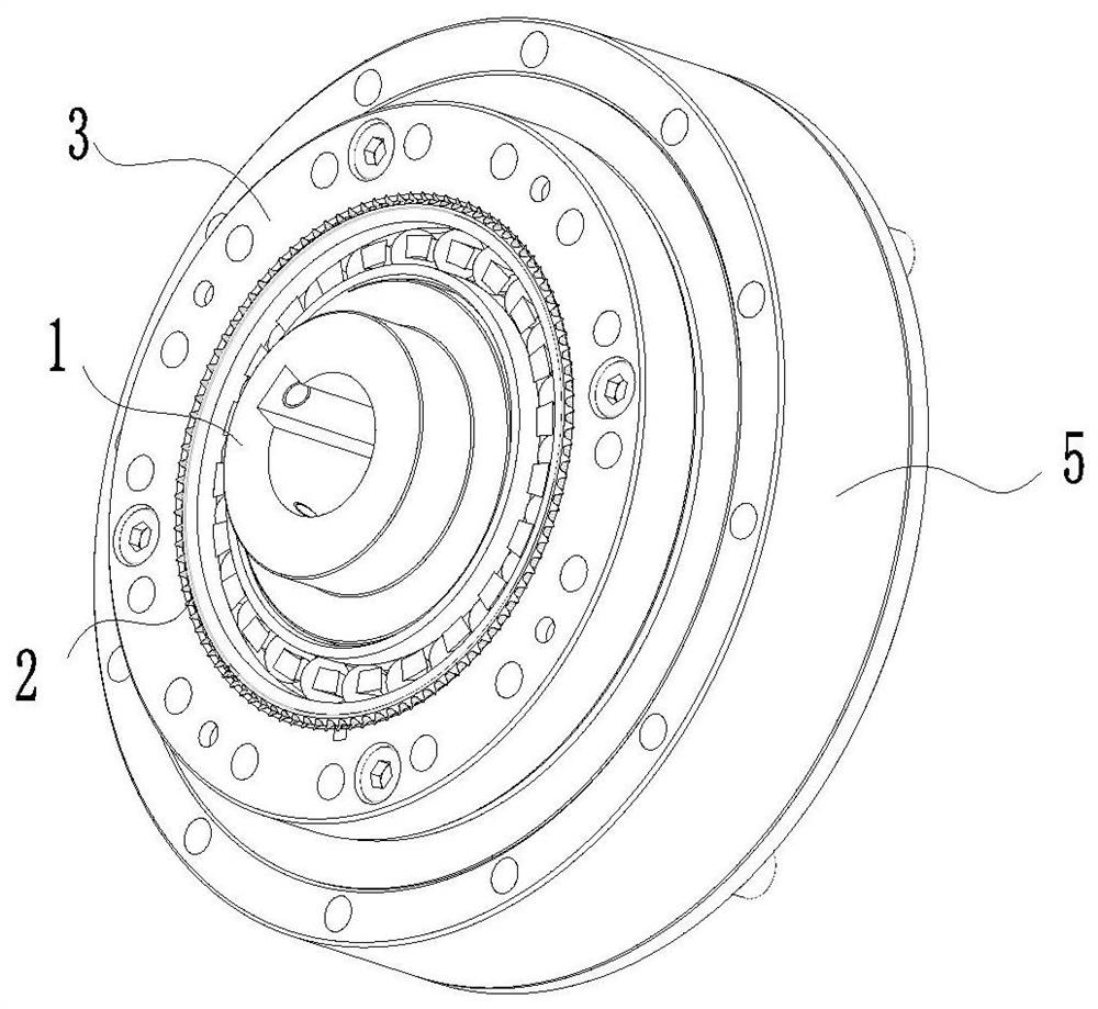
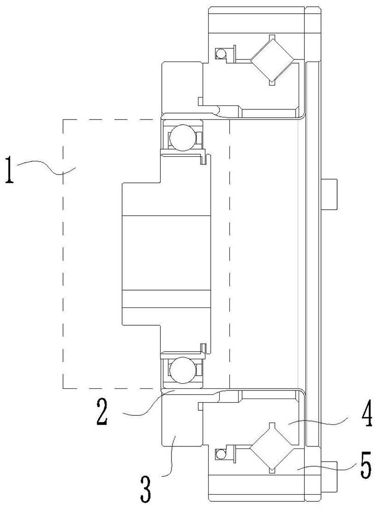
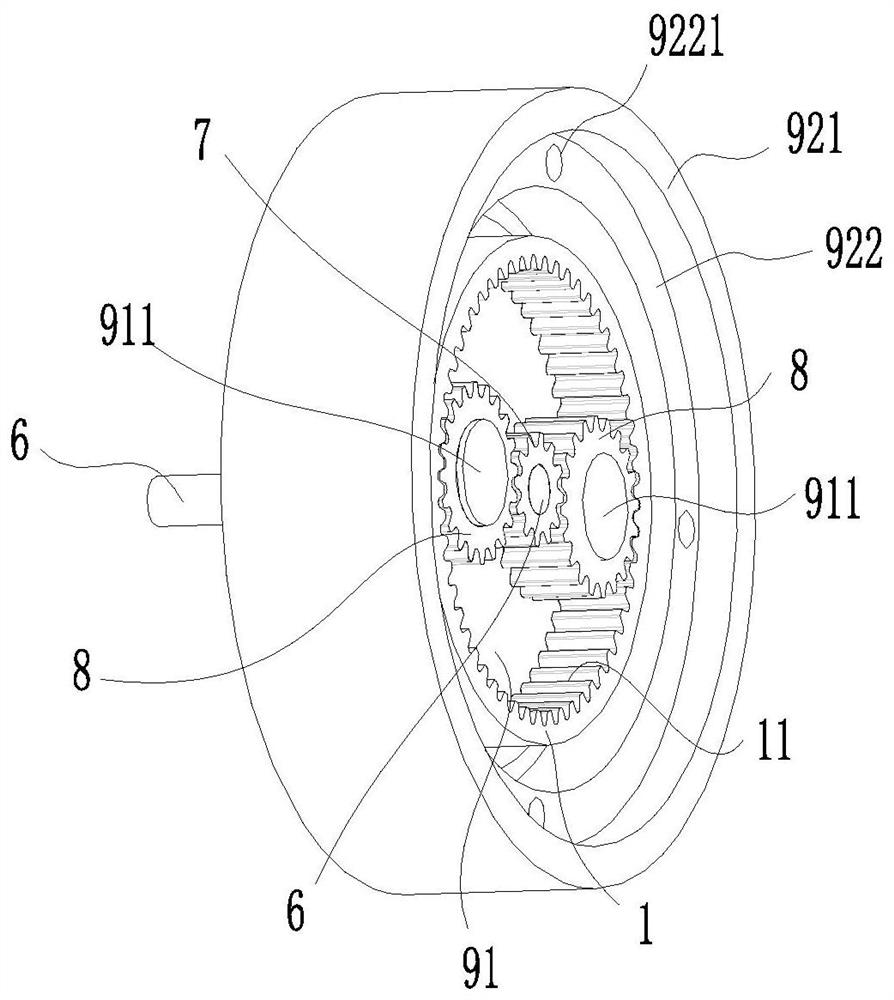
The invention belongs to the technical field of harmonic reducers, and particularly relates to a harmonic reducer adopting multi-stage gear transmission and a robot. The harmonic reducer comprises a first-stage planetary gear transmission mechanism and a second-stage harmonic gear transmission mechanism. The first-stage planetary gear transmission mechanism comprises a wave generator with an innergear, and an input shaft arranged on the wave generator in a penetrating manner. A drive motor is connected to the input end of the input shaft. A sun gear is arranged at the output end. A planetarygear set is arranged between the sun gear and the inner gear of the wave generator. The planetary gear set is engaged with the sun gear and the wave generator at the same time. The second-stage harmonic gear transmission mechanism comprises a flexible wheel. The flexible wheel is connected to the outer side wall of the wave generator in a sleeving manner. According to the harmonic reducer, first-stage planetary gear transmission is added in the wave generator, the speed reduction ratio range of the reducer can be effectively enlarged, and the bearing ability of the whole reducer is enhanced.

Description

technical field [0001] The invention belongs to the technical field of harmonic reducers, and in particular relates to a multi-stage gear-driven harmonic reducer and a robot. Background technique [0002] Because the harmonic reducer has the characteristics of small size, large reduction ratio, large number of meshing teeth at the same time, stable transmission, high bearing capacity, and high transmission precision. Therefore, it is widely used in aerospace, military, industrial robots and other aspects. The harmonic reducer is mainly composed of three major components, namely a wave generator, a flexible spline, and a rigid spline. Since the harmonic transmission mainly relies on the wave generator with an elliptical axis to force the elastic deformation of the flexible spline, and then engages with the rigid spline for transmission, because the flexible spline is a thin-walled structure with a small modulus and a large number of teeth, etc., during the transmission proce...

Claims


Application Information

Patent Timeline
Patent Type & Authority Applications(China)
IPC IPC(8): F16H49/00F16H57/023F16H57/08B25J9/10
CPCB25J9/1025F16H49/001F16H57/023F16H57/082F16H2057/02039F16H2057/02086
Inventor 田珍珍程中甫谷甲甲张皓杨繁荣郭霜
Owner GREE ELECTRIC APPLIANCES INC
Learn More