Circulating heat exchange device and method for improving heat exchange efficiency

A technology of cyclic heat exchange and heat exchange efficiency, which is applied in the direction of air heaters, fluid heaters, lighting and heating equipment, etc., to achieve the effect of shortening the path, avoiding consumption and reducing use

Active Publication Date: 2020-11-17
SHANDONG HUAYU UNIV OF TECH
View PDF7 Cites 1 Cited by
  • Summary
  • Abstract
  • Description
  • Claims
  • Application Information

AI Technical Summary

Problems solved by technology

[0006] The purpose of this disclosure is to provide a circulating heat exchange device and method for improving heat exchange efficiency in view of the defects existing in the prior art. A furnace connected to the outdoor is provided to heat the heat conduction tube and the circulation tube together to form a heat transfer and heat exchange structure, thereby It forms a hot air heating furnace, which does not consume indoor oxygen while outputting hot air, and does not exchange heat for heat exchange. A circulation heating channel is formed inside the circulation pipe, and the airflow output by the return part is reheated, and it is fully mixed with the Venturi tube structure. , improve the efficiency of heat exchange and meet the needs of quick start

Method used


Image

  • Circulating heat exchange device and method for improving heat exchange efficiency
  • Circulating heat exchange device and method for improving heat exchange efficiency

Examples


Embodiment 1

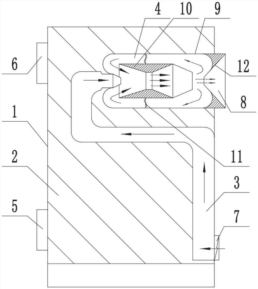
[0038] In a typical implementation of the present disclosure, a circulation heat exchange device for improving heat exchange efficiency is proposed.

[0039] It mainly includes the furnace body 1, the heat conduction pipe 3 and the circulation pipe. The heat conduction pipe and the circulation pipe are arranged in the furnace of the furnace body, and the heat is obtained from the furnace 2, and the air inside the passage is heated and output;

[0040] For the furnace body, it is a shell structure, and the interior of the furnace is a high-temperature resistant structure. In order to ensure that the furnace body will not consume indoor air and affect the indoor environment during operation, an air inlet 5 connected to the furnace body is provided on one side of the furnace body. The air outlet 6, the air inlet and the air outlet are all communicated with the outside, and the air is obtained from the outside, and the exhaust gas after combustion is discharged to the outside, avoi...

Embodiment 2

[0068] In another typical embodiment of the present disclosure, another circulation heat exchange method for improving heat exchange efficiency is provided; it utilizes the circulation heat exchange device for improving heat exchange efficiency described in Embodiment 1.

[0069] Biomass fuel burns in the furnace to release heat, which heats the heat conduction pipe and circulation pipe;

[0070] One end of the heat pipe gets air from the room, and after being heated in the heat pipe, it is input into the circulation pipe;

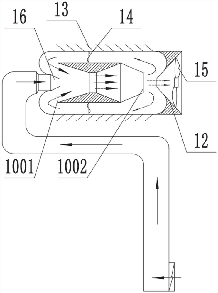
[0071] The air input into the circulation pipe enters the Venturi tube and flows towards the air outlet. When it is discharged from the Venturi tube, part of the air flow is directly output to the room through the air outlet, and the other part enters the circulation channel, and is heated by the return pipe for secondary circulation;

[0072] The heated air flow in the circulation channel enters the Venturi tube together with the air output from the heat ...


PUM


Abstract

The invention provides a circulating heat exchange device and method for improving heat exchange efficiency, and relates to the field of hot air equipment. The circulating heat exchange device comprises a stove body, a heat conduction pipe and a circulating pipe; the heat conduction pipe and the circulating pipe are arranged in a furnace of the stove body, the circulating pipe comprises a venturipipe and a return pipe arranged outside the venturi pipe in a sleeving mode, and one end of the return pipe is connected with the stove body to form an air outlet; the other end of the return pipe isconnected with the heat conduction pipe, a circulation channel is formed between the outer wall of the venturi pipe and the interior of the return pipe, one end of the circulation channel and one endof the heat conduction pipe jointly communicate with an inlet of the venturi pipe, and the air outlet and the other end of the circulation channel jointly communicate with an outlet of the venturi pipe, the furnace communicating with the outside is arranged to heat the heat conduction pipe and the circulating pipe together, indoor oxygen is not consumed while hot air is output, heat exchange is conducted without air exchange, a circulation heating channel is formed inside the circulating pipe, airflow output by the backflow part is subjected to secondary heating, sufficient mixing is conductedin cooperation with the venturi pipe structure, the heat exchange efficiency is improved, and the requirement for rapid starting is met.

Description

technical field [0001] The present disclosure relates to the field of hot air equipment, in particular to a circulating heat exchange device and method for improving heat exchange efficiency. Background technique [0002] The statements in this section merely provide background information related to the present disclosure and may not necessarily constitute prior art. [0003] Biomass hot blast stove refers to the combustion of biomass materials as fuel, so that the energy is supplied to the corresponding equipment in the form of hot air. It is mainly aimed at residents and public buildings that cannot be centrally heated, and provides users with a small, safe, automatic and clean heating method. [0004] Along with the application of biomass, biomass combustion equipment has also been developed rapidly, but most of the equipment now has the problems of low heat exchange efficiency and large energy consumption. [0005] The inventors found that most of the current heating ...

Claims


Application Information

Patent Timeline
Patent Type & Authority Applications(China)
IPC IPC(8): F24H3/02F24H9/00F24H9/12F24H9/18
CPCF24H3/027F24H9/0073F24H9/12F24H9/189
Inventor 孔德霞姚志强
Owner SHANDONG HUAYU UNIV OF TECH
Why Eureka
Try Eureka