
Optical fiber phased array multi-beam scanning system based on array detector

An array detector and beam scanning technology, which is applied in the field of photoelectric detection, can solve the problems of inaccurate multi-beam scanning of optical fiber phased arrays, and achieve the effects of improving accuracy, ensuring output quality, and expanding application scenarios

Active Publication Date: 2020-11-17
XIDIAN UNIV
View PDF4 Cites 12 Cited by
  • Summary
  • Abstract
  • Description
  • Claims
  • Application Information

AI Technical Summary

Problems solved by technology

[0006] The purpose of the present invention is to propose a fiber optic phased array multi-beam scanning system based on an array detector to solve the problem of inaccurate scanning of fiber optic phased array multi-beams in the prior art

Method used


Image

  • Optical fiber phased array multi-beam scanning system based on array detector
  • Optical fiber phased array multi-beam scanning system based on array detector
  • Optical fiber phased array multi-beam scanning system based on array detector

Examples


Embodiment Construction

[0036] The embodiments and effects of the present invention will be further described in detail below in conjunction with the accompanying drawings.

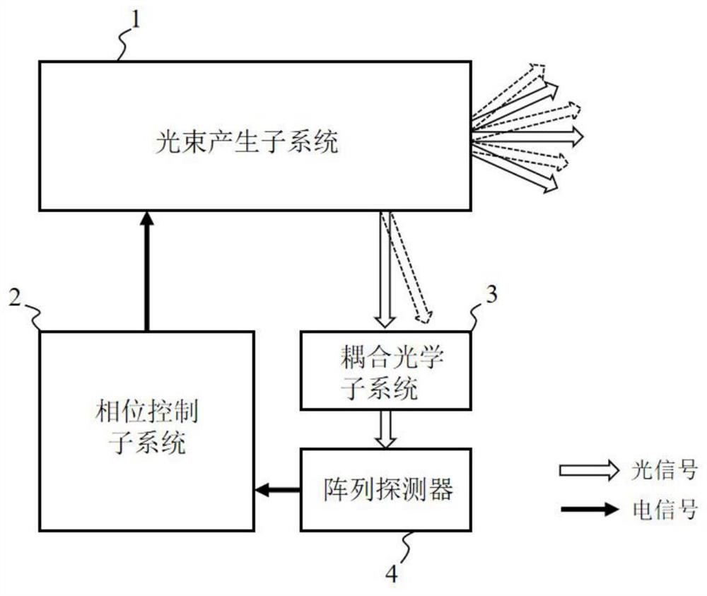
[0037] refer to figure 1 , the optical fiber phased array multi-beam scanning system of the present invention includes beam generation subsystem 1, phase control subsystem 2, coupling optics subsystem 3 and array detector 4; They are respectively connected with the beam generation subsystem 1 and the array detector 4; the coupling optical subsystem 3 is fixed on the array detector 4, and the array detector adopts a plane array detector or a line array detector, and its array elements are distributed as follows: Figure 4 ,in Figure 4 (a) is the distribution of area array detectors, Figure 4 (b) is the distribution of linear array detectors.

[0038] The coupling optical subsystem 3 is composed of multimode optical fiber bundles arranged in space, which are arranged in a rectangular shape according to the beam lattice of the o...


PUM


Abstract

The invention provides an optical fiber phased array multi-beam scanning system based on an array detector, which mainly solves the accuracy problem of beam scanning and comprises a beam generation subsystem (1), a phase control subsystem (2), a coupling optical subsystem (3) and the array detector (4). The coupling optical subsystem is a multi-mode optical fiber bundle arranged in space, the array detector is a linear array or area array detector, and central sub-view-field sampling output by the optical fiber phased array is achieved in a matched mode. Phase noise compensation is carried outthrough a phase control subsystem (based on an SPGD algorithm) according to the light beam space scanning time sequence to form a to-be-scanned multi-light-beam dot matrix; and then a preset scanningvoltage is applied to the multiple paths of optical fiber light beams, and if the light intensity sampling of the array detector is lower than a threshold value, scanning voltage fine tuning calibration at a corresponding position is performed by utilizing a phase control subsystem. Phase feedback control is performed by using the array detector, and accurate pointing of space and rapid coverageof a field of view are simultaneously realized through multi-beam scanning.

Description

technical field [0001] The invention belongs to the technical field of photoelectric detection, and in particular relates to an optical fiber phased array scanning system, which can be used for multi-beam scanning to simultaneously realize accurate spatial orientation and fast coverage of a field of view. [0002] technical background [0003] Beam scanning technology is a technology that precisely controls and positions the direction of the laser beam. Common beam scanning technologies include mechanical, micro-electromechanical and purely electronic control. Optical fiber phased array belongs to pure electric control type. Compared with mechanical type and micro-electromechanical type, optical fiber phased array has the characteristics of small inertia, fast scanning speed and high sensitivity. It is used in high-energy laser synthesis, multi-target detection and tracking, It has been widely used in complex target imaging and other fields. However, the optical fiber phase...

Claims


Application Information

Patent Timeline
Patent Type & Authority Applications(China)
IPC IPC(8): G01S7/484
CPCG01S7/484
Inventor 刘春波王晓斌卢芳李祺伟韩香娥
Owner XIDIAN UNIV
Learn More