A protection switching method and communication device of a pipeline mechanism

A technology for protection switching and communication equipment, applied in the field of Ethernet, can solve the problems of long protection switching time, reducing the protection group polling cycle, and the number of protection groups cannot meet business needs, so as to reduce the polling cycle and shorten the time Effect

Active Publication Date: 2022-04-19
FENGHUO COMM SCI & TECH CO LTD
View PDF8 Cites 0 Cited by
  • Summary
  • Abstract
  • Description
  • Claims
  • Application Information

AI Technical Summary

Problems solved by technology

[0006] In view of the above defects or improvement needs of the prior art, the present invention provides a protection switching method and communication equipment with a pipeline mechanism, the purpose of which is to execute the protection switching of the protection group in parallel, which can greatly reduce the polling cycle of the protection group , to shorten the protection switching time, thereby solving the technical problems that the current protection switching time is too long, and the number of protection groups that a single device can support cannot meet business needs

Method used


Image

  • A protection switching method and communication device of a pipeline mechanism
  • A protection switching method and communication device of a pipeline mechanism
  • A protection switching method and communication device of a pipeline mechanism

Examples


Embodiment 1

[0056] At present, a solution of executing a protection switching state machine realized by software on a CPU is adopted to meet service requirements of protection switching. Since the software logic can only be executed serially on the CPU, the logic that is originally not bound to the sequence of execution must also be executed serially, thereby reducing the operating efficiency of the state machine; and the ALU (Arithmetic and LogicUnit, abbreviated as ALU) in the CPU ) does not specifically design the data path for the protection switching state machine algorithm. Software developers need to decompose the dedicated logic of the protection switching state machine into multiple logic combinations in the CPU instruction set to run on the CPU, making the final logic chain lengthy. Further reduce the operating efficiency of the state machine. The polling period of the protection switching state machine finally implemented by software is often at the millisecond level. For the ...

Embodiment 2

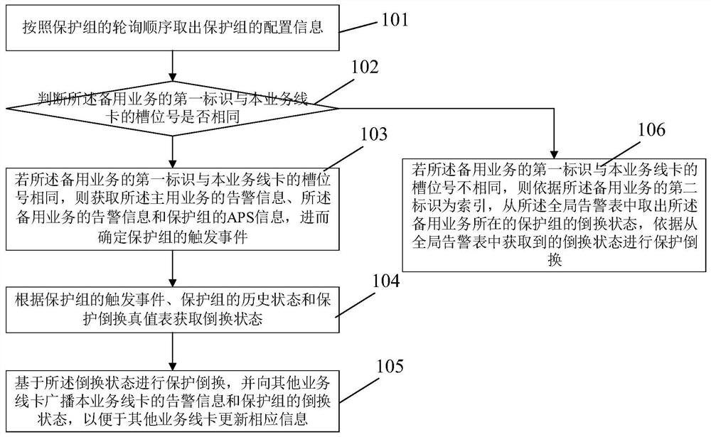
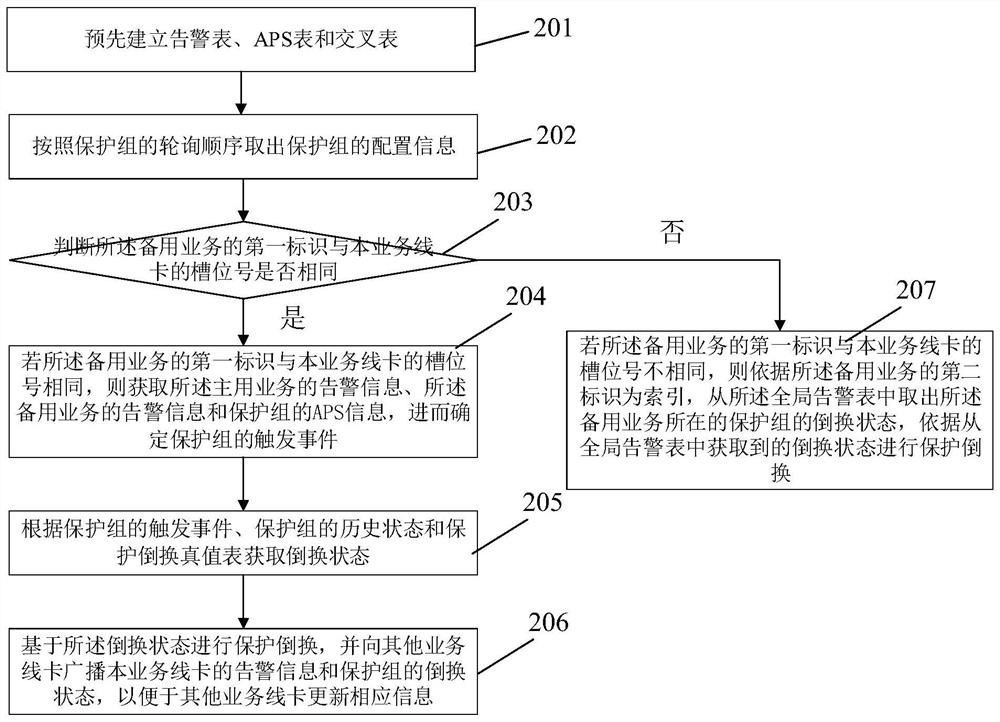
[0082] In conjunction with embodiment 1, refer to figure 2 , this embodiment illustrates the specific execution process of the protection switching method:

[0083] Step 201: Pre-establish a local alarm table, an APS table and a global alarm table.

[0084] In this embodiment, each service is configured with a first identifier, a second identifier, and a third identifier, wherein the first identifier is the same as the slot number of the service line card where the service is located, and the service can be determined through the first identifier. The service line card where it is located, the second identifier is globally unique on the communication device, the second identifier is used to distinguish different services of the same device, and the third identifier is unique on the corresponding service line card property, the third identifier is used to distinguish different services located on the same service line card. For example, when using the distributed OAM (Operat...

Embodiment 3

[0126] The aforementioned embodiment 1 and embodiment 2 mainly describe the specific execution process of the protection switching method. Correspondingly, this embodiment provides a communication device that combines Figure 4 , the communication device includes a plurality of service line cards, each of which carries a plurality of services, and each of the service line cards is provided with a plurality of protection groups, and each protection group includes a main service and a backup For the main service and backup service of a protection group, the main service and the backup service can be located on the same service line card or on different service line cards.

[0127] Each of the service line cards includes an FPGA device, and the FPGA device is provided with a protection switching state machine, and the protection switching state machine is used to implement the protection switching method described in the foregoing embodiment 1 and embodiment 2.

[0128] The commu...


PUM


Abstract

The invention discloses a protection switching method of a pipeline mechanism and a communication device. The protection switching method includes: taking out the configuration information of the protection group according to the polling sequence of the protection group, wherein the configuration information of the protection group includes the first identification of the main service and the first identifier of the backup service, the first identifier is the same as the slot number of the service line card where the service is located; judge whether the first identifier of the backup service is the same as the slot number of the service line card; if the first identifier of the backup service If the slot number of the service line card is the same as that of the service line card, the alarm information of the active service, the alarm information of the backup service, and the APS information of the protection group are obtained, and then the trigger event of the protection group is determined; according to the trigger event of the protection group, the The historical state and the protection switching truth table obtain the switching state; perform protection switching based on the switching state, and broadcast the alarm information of the service line card and the switching state of the protection group to other service line cards, so that other service line cards can update the corresponding information.

Description

technical field [0001] The invention belongs to the field of Ethernet, and more specifically relates to a protection switching method and communication equipment of a pipeline mechanism. Background technique [0002] At present, Slicing Packet Network (abbreviated as SPN) is the network architecture determined by China Mobile to support 5G transmission and bearer. Compared with the previous generation of PTN (Packet Transport Network, abbreviated as PTN) technology, its impact on bandwidth, Delay, time synchronization and QoS (Quality of Service, QoS for short) have higher requirements. SPN uses FlexE technology to split a large physical link into several smaller physical channels, or vice versa, to ensure QoS and service slice isolation between transport layers. [0003] Automatic Protection Switching (APS for short) is a linear protection mechanism applied to Ethernet. By binding two service flows into an active / standby protection group, it can automatically switch betwee...

Claims


Application Information

Patent Timeline
Patent Type & Authority Patents(China)
IPC IPC(8): H04L41/0663H04L41/0631
CPCH04L41/0663H04L41/0631
Inventor 陈九州
Owner FENGHUO COMM SCI & TECH CO LTD
Why Eureka
Try Eureka