Supercharge Your Innovation With Domain-Expert AI Agents!

Method for controlling distance between light-emitting element and photosensitive element and optocoupler structure

A technology of photosensitive elements and light-emitting elements, which is applied to printed circuits connected to non-printed electrical elements, components of control amplifiers, and electrical elements, etc., can solve problems such as difficulties in on-site installation and debugging, and achieve the solution of difficult installation and debugging, The effect of improving installation efficiency and output resistance consistency, reducing installation requirements and difficulty of assembly and debugging

Pending Publication Date: 2020-11-17
贵州航天凯山石油仪器有限公司
View PDF0 Cites 0 Cited by
  • Summary
  • Abstract
  • Description
  • Claims
  • Application Information

AI Technical Summary

Problems solved by technology

[0003] The purpose of the present invention is to provide a method for controlling the distance between the light-emitting element and the photosensitive element and an optocoupler structure, so as to reduce the welding requirements and the difficulty of assembly and debugging, so as to solve the problem of difficulty in on-site installation and debugging and the shortcomings of the prior art

Method used


Image

  • Method for controlling distance between light-emitting element and photosensitive element and optocoupler structure

Examples


Embodiment

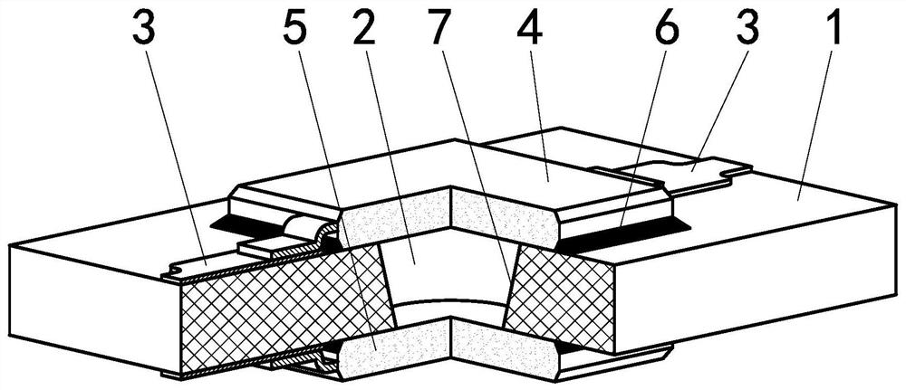
[0021] This example figure 1 As shown, the chip photoresistor 4 is included, and the chip photoresistor 4 is welded on the top surface of the printed board 1, and is welded on the bottom surface of the printed board 1 with a patch highlight lamp bead 5, and assembled together into an optocoupler structure. The printed board 1 is provided with a conical hole 2, and the top and bottom surfaces of the conical hole 2 are provided with a pad 3 and lead-out patch pins, wherein the pad 3 is used for welding the chip photoresistor 4 and the patch highlight Lamp bead 5, and the four SMD pins have two for the input of the optocoupler, and the other two are used for the output of the optocoupler.

[0022] This example is mainly to improve the optocoupler packaging method. The specific implementation is as follows: figure 1 As shown, the conical ring surface in the printed board can be drilled with a drill bit and metalized through the hole, and then the two components are directly welde...


PUM


Abstract

The invention discloses a method for controlling the distance between a light-emitting element and a light-sensitive element and an optical coupling structure, and the method comprises the steps: drilling a conical hole in a printed board, enabling a patch light-sensitive element and a patch light-emitting element to be respectively attached to two sides of the conical hole, and welding the patchlight-sensitive element and the patch light-emitting element on a bonding pad of the printed board; and controlling the distance between the light-emitting element and the photosensitive element by utilizing the thickness of the printed board. Through improvement of an optocoupler packaging mode, only the patch high-brightness lamp beads and the patch photoresistors need to be mounted in sequenceduring assembly, and the distance between the two components does not need to be adjusted without direct insertion of the components, so the mounting requirement and the assembling and debugging difficulty are reduced, the mounting efficiency and the output resistance consistency are improved, the production cost is reduced, and the problem of difficulty in field installation and debugging is solved.

Description

technical field [0001] The invention relates to a method for controlling the distance between a light-emitting element and a photosensitive element and an optocoupler structure, belonging to the technical field of optocoupler element production. Background technique [0002] Most of the liquid level testers used in the oil field testing oil well casing annulus use a liquid level tester. The liquid level signal used by this tester needs to use a filter amplifier board. The amplifier board uses an optocoupler to automatically adjust the amplification gain. The optocoupler components currently purchased in the market are usually composed of in-line photoresistors and in-line diodes. Because it is difficult to control the distance between the diode and the photoresistor by in-line diode welding, the output resistance of the optocoupler produced by this method varies greatly under the same voltage input condition, which will bury hidden dangers for later application, and it is di...

Claims


Application Information

Patent Timeline
IPC IPC(8): H05K1/18H05K1/11H03G1/00
CPCH03G1/00H05K1/116H05K1/185
Inventor 钟昌洪程凯
Owner 贵州航天凯山石油仪器有限公司
Features
  • R&D
  • Intellectual Property
  • Life Sciences
  • Materials
  • Tech Scout
  • Unparalleled Data Quality
  • Higher Quality Content
  • 60% Fewer Hallucinations
Learn More