
Efficient and rapid impurity separation centrifugal pulp cleaner for factory

An efficient and fast technology, applied in the direction of centrifuges, supporting machines, engine frames, etc., can solve the problems of throwing fibers and impurities out of the device and reducing the working efficiency of the device, so as to improve efficiency, reduce movement offset and improve stability sexual effect

Inactive Publication Date: 2020-11-20
GANSU PULUO BIOTECH
View PDF8 Cites 1 Cited by
  • Summary
  • Abstract
  • Description
  • Claims
  • Application Information

AI Technical Summary

Problems solved by technology

[0004] The purpose of the present invention is to provide a kind of centrifugal slag remover that is used in factories to efficiently and quickly separate impurities, so as to solve the problem that there are often some large-particle fibers in the slurry proposed in the above-mentioned background technology, which leads to the occurrence of fibers with larger particles. and impurities are thrown out of the device together. At this time, it is often necessary to perform slag removal on the slurry twice, which greatly reduces the working efficiency of the device.

Method used


Image

  • Efficient and rapid impurity separation centrifugal pulp cleaner for factory
  • Efficient and rapid impurity separation centrifugal pulp cleaner for factory
  • Efficient and rapid impurity separation centrifugal pulp cleaner for factory

Examples

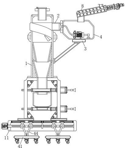
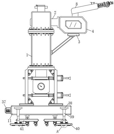
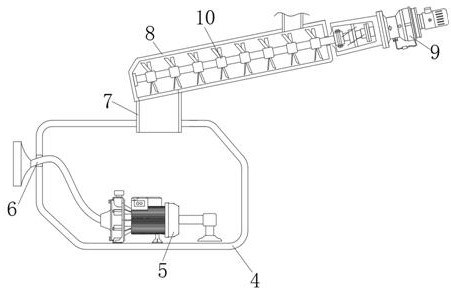

Embodiment Construction

[0025] The following will clearly and completely describe the technical solutions in the embodiments of the present invention with reference to the accompanying drawings in the embodiments of the present invention. Obviously, the described embodiments are only some, not all, embodiments of the present invention. Based on the embodiments of the present invention, all other embodiments obtained by persons of ordinary skill in the art without making creative efforts belong to the protection scope of the present invention.

[0026] see Figure 1-7 , an embodiment provided by the present invention:

[0027]A centrifugal slag remover for efficient and rapid separation of impurities in factories, comprising a slag remover body 1, a feed port 2 and a control panel 37, a support frame 3 is fixedly installed on the right side of the slag remover body 1, and the top of the support frame 3 The first treatment box 4 is fixedly installed, and the inside of the first treatment box 4 is fixe...


PUM


Abstract

The invention discloses an efficient and rapid impurity separation centrifugal pulp cleaner for a factory. The efficient and rapid impurity separation centrifugal pulp cleaner comprises a pulp cleanerbody, a feed port and a control panel. A supporting frame is fixedly mounted on the right side of the pulp cleaner body. A first treatment box is fixedly mounted at the top end of the supporting frame. A pulp injection pump is fixedly mounted in the first treatment box. A delivery pipe is fixedly mounted at the left end of the pulp injection pump. According to the efficient and rapid impurity separation centrifugal pulp cleaner, a driving motor rotates to drive a crushing shaft to rotate to crush big-particle objects in pulp, the crushed pulp flows from a discharge port of a second treatmentbox into the first treatment box, and the pulp in the first treatment box is pumped out through the pulp injection pump and goes into the pulp cleaner body through the delivery pipe and the feed port.The efficient and rapid impurity separation centrifugal pulp cleaner can conduct pretreatment on the pulp waiting for residual removal. Accordingly, the situation that big-particle fibers are thrownout of the device and need to be subjected to secondary residual removal treatment is reduced. Therefore, the pulp residual removal efficiency of the efficient and rapid impurity separation centrifugal pulp cleaner is improved.

Description

technical field [0001] The invention relates to the technical field of slag removers, in particular to a centrifugal slag remover for efficient and rapid separation of impurities in factories. Background technique [0002] Slag remover is a kind of equipment that uses centrifugal principle to remove impurities with different density in slurry. The upper part of the slag remover is made of stainless steel, and the lower part is made of polyurethane material. The inner wall of the main body is designed as a spiral cone. The principle is to separate impurities by using the different specific gravity of fibers and impurities. The slurry enters the slag remover from the feeding tee tangent at a certain pressure and then rotates at a high speed. Due to the difference in centrifugal force, the heavy impurities are thrown to the wall of the device. Under the action of gravity, they gradually move to the bottom of the cone and enter the sediment tank. Due to the small centrifugal fo...

Claims


Application Information

Patent Timeline
IPC IPC(8): B04B5/10B04B7/00B04B15/00B04B11/04F16M3/00
CPCB04B5/10B04B7/00B04B11/04B04B15/00B04B2005/105F16M3/00
Inventor 康尚云马金勇
Owner GANSU PULUO BIOTECH
Learn More