Supercharge Your Innovation With Domain-Expert AI Agents!

Fluid drive device and power generator with same

A fluid-driven and fluid-driven technology, applied in the field of generators, can solve the problems of insufficient and effective utilization of hydraulic residual energy, insufficient and effective utilization of residual heat, etc., and achieve easy access, tight spacing, and increased contact area. big effect

Inactive Publication Date: 2020-11-20
深圳朴坂科技有限公司
View PDF0 Cites 1 Cited by
  • Summary
  • Abstract
  • Description
  • Claims
  • Application Information

AI Technical Summary

Problems solved by technology

[0002] With the rapid development of the national economy, the demand for electric energy is increasing. The conventional power generation methods commonly used at present, such as coal-fired power generation and hydropower generation, require special power equipment to drive generators to generate electricity, such as water conservancy To generate electricity, it is necessary to build a dam to generate electricity, which is not only expensive, but also cannot be moved, and the residual energy of hydraulic power after power generation cannot be fully and effectively utilized. Another example is coal-fired power generation, which needs to be burned to drive the generator to generate electricity, which is not only large in size and complex in structure , is not easy to move, waste heat cannot be fully and effectively utilized, and there will also be environmental pollution problems. The conventional power generation methods described above all have complex structures, poor reliability, high cost, and are not easy to move, and the surplus energy after power generation cannot be Make full use of the disadvantages such as

Method used


Image

  • Fluid drive device and power generator with same
  • Fluid drive device and power generator with same
  • Fluid drive device and power generator with same

Examples


Embodiment Construction

[0031] In order to enable those skilled in the art to better understand the technical solution of the present invention, the technical solution of the present application will be described in detail below in conjunction with the accompanying drawings and specific implementation methods.

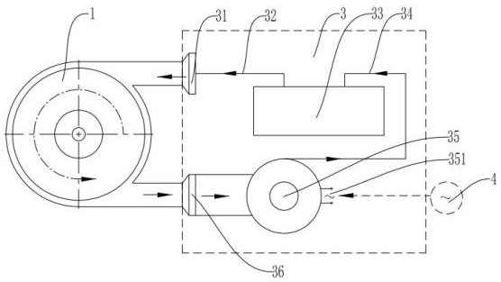
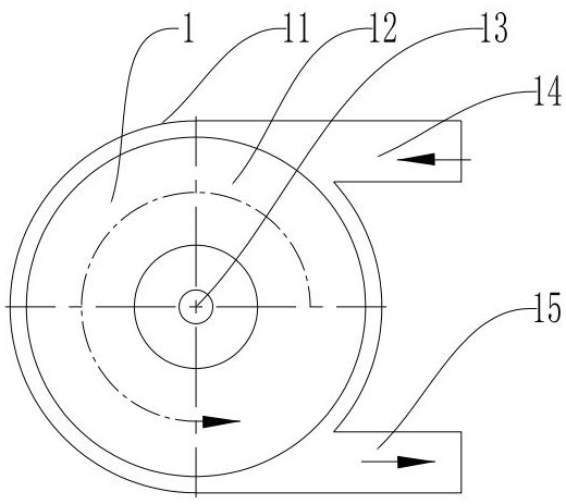
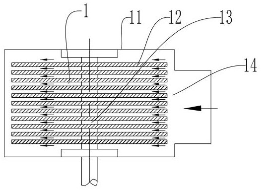
[0032] Such as figure 1 As shown, a fluid driving device includes a fluid driver 1 and a fluid circulation system 3. The connection between the fluid circulation system 3 and the fluid driver 1 is an airtight communication connection, and the fluid flows in the fluid circulation system 3. After being pressed, it is sprayed into the fluid driver 1, and through contact with the surface of the driving part of the fluid driver 1, the generated frictional force pushes the driving part to rotate, thereby driving the fluid driver 1 to run.

[0033] In order to simplify the structure of the fluid driver, improve operational reliability, and reduce the manufacturing and maintenance costs of the fluid ...


PUM

PropertyMeasurementUnit
Thicknessaaaaaaaaaa

Abstract

The invention discloses a fluid drive device. The fluid drive device comprises a fluid driver and a fluid circulating system. The fluid circulating system communicates with the fluid driver in a closed loop, fluid flows in the fluid circulating system, after being cyclically pressurized, the fluid is sprayed into the fluid driver, a drive part is pushed to rotate through friction force generated when the fluid makes contact with the surface of the drive part of the fluid driver, and therefore the fluid driver is driven to operate. By the adoption of the scheme, as the fluid flows in the fluidcirculating system, the fluid is cyclically pressurized to be sprayed into the fluid driver, the fluid driver is pushed to rotate through the friction force generated when the fluid makes contact withthe driver, thus, a power generator coaxially connected with the fluid drive device is driven to generate power, the structure is simple, and the use operation reliability is high.

Description

technical field [0001] The invention relates to the technical field of machinery and power generation, in particular to a fluid drive device and a generator using the drive device. Background technique [0002] With the rapid development of the national economy, the demand for electric energy is increasing. The conventional power generation methods commonly used at present, such as coal-fired power generation and hydropower generation, require special power equipment to drive generators to generate electricity, such as water conservancy To generate electricity, it is necessary to build a dam to generate electricity, which is not only expensive, but also cannot be moved, and the residual energy of hydraulic power after power generation cannot be fully and effectively utilized. Another example is coal-fired power generation, which needs to be burned to drive the generator to generate electricity, which is not only large in size and complex in structure , is not easy to move, w...

Claims


Application Information

Patent Timeline
IPC IPC(8): F01K25/10F01D1/36F01D5/06F01D5/02F01D15/10F03B5/00F03B13/06
CPCF01D1/36F01D5/028F01D5/06F01D15/10F01K25/103F03B5/00F03B13/06Y02E10/20Y02E60/16
Inventor 李隆毅
Owner 深圳朴坂科技有限公司
Features
  • R&D
  • Intellectual Property
  • Life Sciences
  • Materials
  • Tech Scout
  • Unparalleled Data Quality
  • Higher Quality Content
  • 60% Fewer Hallucinations
Learn More