Self-adjusting heat dissipation system of experimental machine room server based on NFC technology

A technology of cooling system and server, applied in the field of NFC technology server, can solve the problems of inability to adjust the rotation speed, economic loss, slow rotation speed, etc., and achieve the effect of better cooling effect, fast air convection, and accelerated floating

Inactive Publication Date: 2020-11-20
何风辰
View PDF0 Cites 0 Cited by
  • Summary
  • Abstract
  • Description
  • Claims
  • Application Information

AI Technical Summary

Problems solved by technology

[0003] During the use of existing servers, because the internal components are too complex, and the electronic components have high precision and relatively concentrated distribution, a large amount of heat will be generated during work. If the heat inside the chassis cannot be discharged in time, It is easy to burn out the internal electrical components. On the one hand, it will cause serious economic losses. On the other hand, it will have an adverse effect on the development of NFC technology. Therefore, it is necessary to dissipate heat inside the chassis. Only through the air vents, the natural convection of the air cannot meet the heat dissipation requirements inside the chassis. Although the cooling effect of the fans is better than that of the air vents, the speed of the existing fans cannot be based on the heat dissipation. The temperature inside the chassis is adjusted. When the temperature inside the chassis is too high, the speed is too slow to meet the heat dissipation requirements inside the chassis. Therefore, it is necessary to design a self-regulating heat dissipation system based on the NFC technology experimental computer room server to solve the above problems.

Method used


Image

  • Self-adjusting heat dissipation system of experimental machine room server based on NFC technology
  • Self-adjusting heat dissipation system of experimental machine room server based on NFC technology
  • Self-adjusting heat dissipation system of experimental machine room server based on NFC technology

Examples


Embodiment Construction

[0018] The following will clearly and completely describe the technical solutions in the embodiments of the present invention with reference to the accompanying drawings in the embodiments of the present invention. Obviously, the described embodiments are only some, not all, embodiments of the present invention.

[0019] In describing the present invention, it should be understood that the terms "upper", "lower", "front", "rear", "left", "right", "top", "bottom", "inner", " The orientation or positional relationship indicated by "outside", etc. is based on the orientation or positional relationship shown in the drawings, and is only for the convenience of describing the present invention and simplifying the description, rather than indicating or implying that the referred device or element must have a specific orientation, so as to Specific orientation configurations and operations, therefore, are not to be construed as limitations on the invention.

[0020] refer to Figure ...


PUM


Abstract

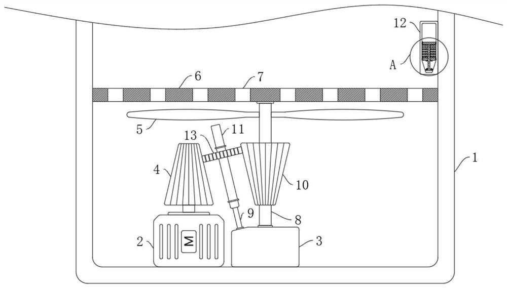
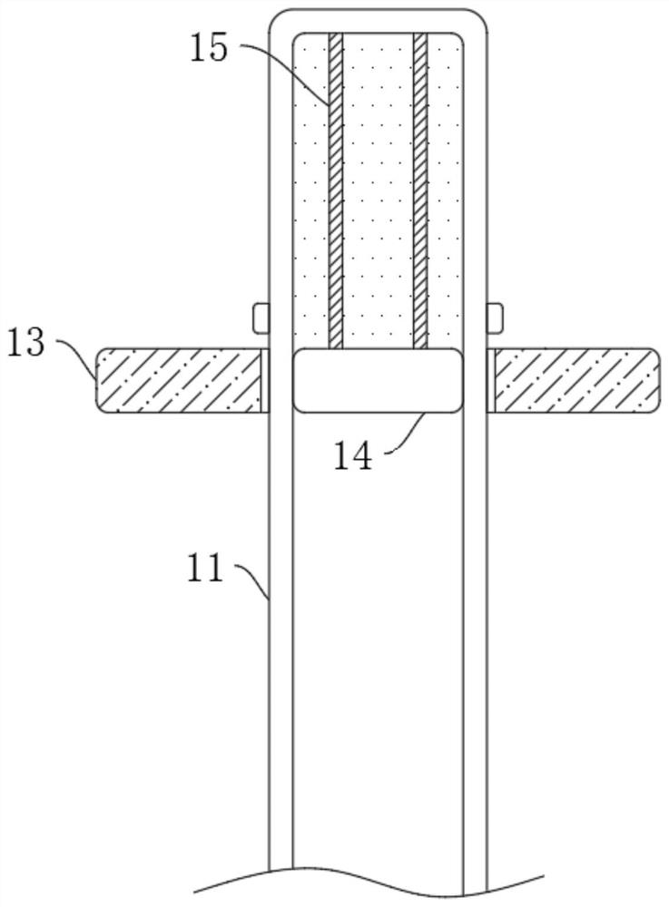
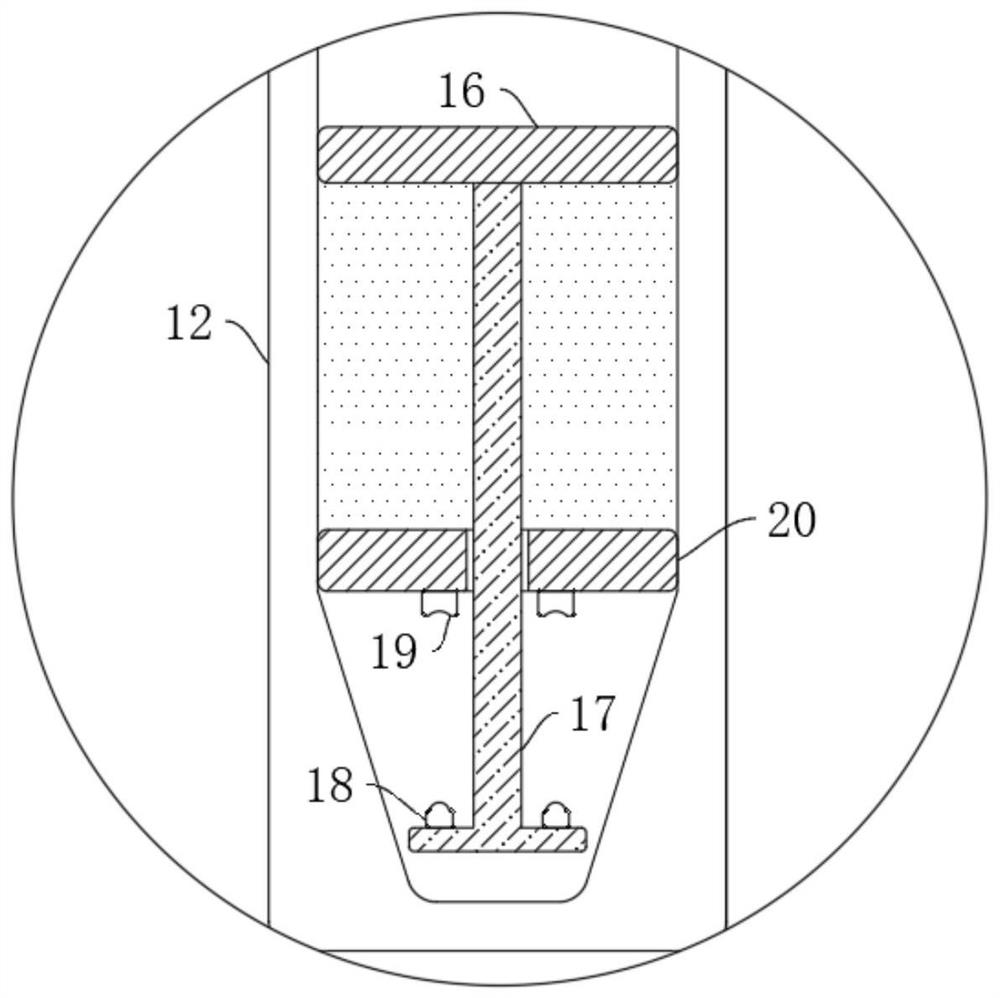
The invention discloses a self-adjusting heat dissipation system of an experimental machine room server based on an NFC technology. The system includes a case, a placing plate is fixedly connected tothe inner wall of the case; a plurality of ventilation holes are formed in the side wall of the placing plate in a penetrating manner; a motor is fixedly connected to the bottom in the case; the lowerwall of the placing plate is rotationally connected with a rotating shaft through a bearing; a plurality of fan blades are fixedly connected to the side wall of the rotating shaft; a control mechanism used for controlling on-off of the motor is arranged in the machine box, a speed adjusting mechanism used for adjusting the rotating speed of the fan blades is arranged in the machine box, the speedadjusting mechanism comprises a driving gear fixedly connected to an output shaft of the motor, a rotating rod capable of rotating is arranged in the machine box, and a rotating cylinder is fixedly connected to the upper end of the rotating rod. According to the system, the interior of the computer case can be effectively cooled, the rotating speed of the fan blades can be adjusted according to the temperature in the computer case, the higher the temperature is, the higher the rotating speed is, and the heat dissipation effect of the device on the interior of the computer case is better.

Description

technical field [0001] The invention relates to the technical field of NFC technology servers, in particular to a self-regulating heat dissipation system based on NFC technology experiment room servers. Background technique [0002] NFC (Near Field Communication), that is, near field communication, is an emerging technology. Devices using NFC technology (such as mobile phones) can exchange data when they are close to each other. It is a non-contact radio frequency identification (RFID ) and the integration of interconnection and intercommunication technology, through the integration of inductive card readers, inductive cards and point-to-point communication functions on a single chip, and in the experimental computer room developed by NFC technology, some development of NFC technology needs to be used server. [0003] During the use of existing servers, because the internal components are too complex, and the electronic components have high precision and relatively concentr...

Claims


Application Information

Patent Timeline
IPC IPC(8): G06F1/20G06F1/18
CPCG06F1/183G06F1/20G06F2200/201
Inventor 何风辰胡传艳
Owner 何风辰
Why Eureka
Try Eureka