Device and method for broadening high-energy excimer laser pulses
An excimer laser and pulse broadening technology, applied in lasers, phonon exciters, laser parts, etc., can solve the problem of limiting the use effect, error and control difficulty of pulse broadening devices, affecting the exposure performance and product quality of lithography machines, etc. question
- Summary
- Abstract
- Description
- Claims
- Application Information
AI Technical Summary
Problems solved by technology
Method used
Image
Examples
Embodiment 1
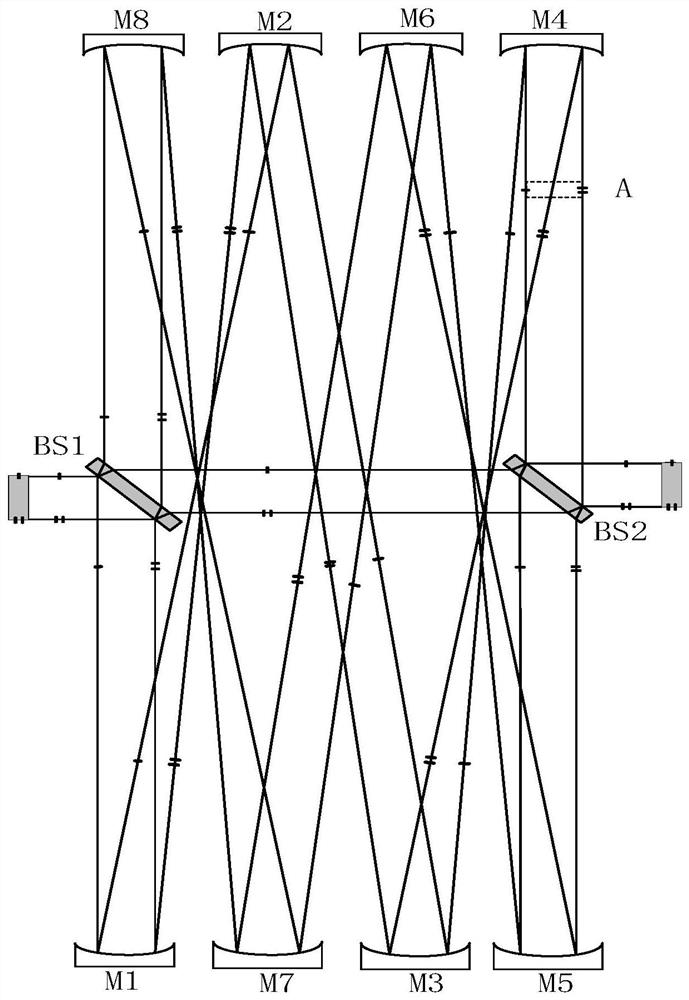
[0031] like figure 1As shown, the excimer laser pulse stretching device based on two beam-splitting elements and eight spherical mirrors to form an optical delay cavity in this embodiment is composed of the first beam-splitting element BS1, the second beam-splitting element BS2 (the first The first beam-splitting element BS1 and the second beam-splitting element BS2 are both 45-degree beam-splitting elements), spherical mirror M1, spherical mirror M2, spherical mirror M3, spherical mirror M4, spherical mirror M5, spherical mirror M6, spherical mirror M7, spherical mirror M8.
[0032] The input beam is first split into two beams by the first beam splitting element BS1, namely the transmitted beam and the reflected beam. The transmitted beam is directly incident on the second beam splitting element BS2 for further splitting, and the reflected beam is also incident on the second beam splitting element BS2 for further splitting after being optically delayed by the spherical mirro...
Embodiment 2
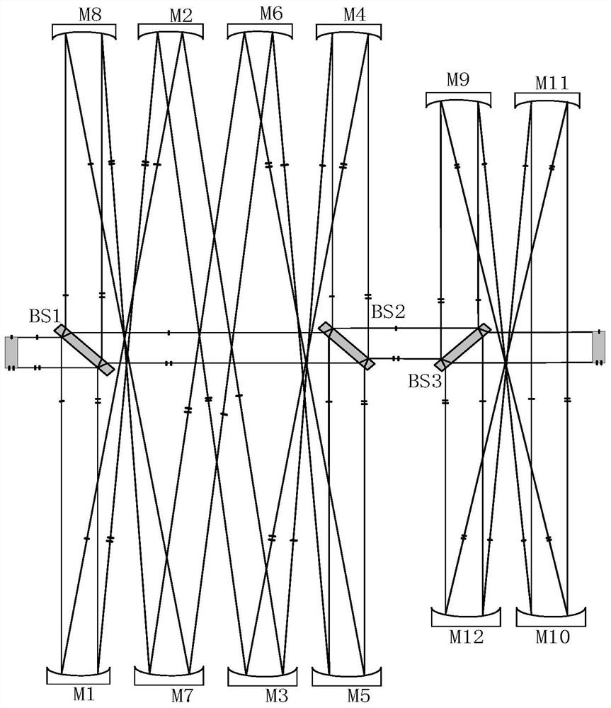
[0036] In order to further improve the pulse stretching ratio, the excimer laser pulse stretching device based on two beam splitting elements and eight spherical mirrors used in the present invention to form an optical delay cavity and the device based on a single beam splitting element and four spherical mirrors to form an optical delay cavity Excimer laser pulse stretching devices are used in series, such as figure 2 As shown, the output beam through the optical delay cavity is consistent with the input beam directly passing through the beam splitting element BS1, the beam splitting element BS2, and the output beam of the beam splitting element BS3 in terms of spot size, beam divergence angle, beam drift and other characteristic parameters.
[0037] The radius of curvature of the spherical reflector in the excimer laser pulse stretching device used in this embodiment is related to the length of the optical delay cavity. When optimizing the radius of curvature of the spherica...
Embodiment 3
[0039] In order to further illustrate the necessity of the number of mirrors in the optical delay cavity being 8, image 3 In order to adopt an excimer laser pulse stretching device based on two beam splitting elements and four spherical mirrors to form an optical delay cavity, a part of the beam in the input beam is reflected by the beam splitting element BS4, spherical mirror M13, spherical mirror M14 reflection and beam splitting Component BS5 reflection, after an even number of (four) mirror reflections and an odd number of (one) imaging, the output beam formed is an inverted image of the input beam, resulting in the final output beam including two beams of the normal image and the inverted image. When the pointing of the input beam drifts, the pointing drift of the output beam will increase exponentially, resulting in poor pointing stability of the input beam after passing through the excimer laser pulse stretching device.
[0040] same, Figure 4 In order to adopt an ex...
PUM
 Abstract
Description
Claims
Application Information
 - R&D
- Intellectual Property
- Life Sciences
- Materials
- Tech Scout
- Unparalleled Data Quality
- Higher Quality Content
- 60% Fewer Hallucinations
Browse by: Latest US Patents, China's latest patents, Technical Efficacy Thesaurus, Application Domain, Technology Topic, Popular Technical Reports.
© 2025 PatSnap. All rights reserved.Legal|Privacy policy|Modern Slavery Act Transparency Statement|Sitemap|About US| Contact US: help@patsnap.com


