Interference velocity measurement system and method

A speed measurement and interference signal technology, which is applied in radio wave measurement systems, measurement devices, electromagnetic wave re-radiation, etc., can solve the problems of low upper limit of speed measurement and difficulty in improving time resolution ability, so as to reduce bandwidth requirements, improve time resolution and Effect of upper limit on speed measurement

Inactive Publication Date: 2016-11-09
INST OF FLUID PHYSICS CHINA ACAD OF ENG PHYSICS
View PDF2 Cites 8 Cited by
  • Summary
  • Abstract
  • Description
  • Claims
  • Application Information

AI Technical Summary

Problems solved by technology

However, due to the limitation of the bandwidth of existing photodetectors and oscilloscopes, it is difficult to improve the time resolution capability and the upper limit of speed measurement is low

Method used


Image

  • Interference velocity measurement system and method
  • Interference velocity measurement system and method
  • Interference velocity measurement system and method

Examples


Embodiment Construction

[0020] In order to make the purpose, technical solutions and advantages of the embodiments of the present invention clearer, the technical solutions in the embodiments of the present invention will be clearly and completely described below in conjunction with the drawings in the embodiments of the present invention. Obviously, the described embodiments It is a part of embodiments of the present invention, but not all embodiments. The components of the embodiments of the invention generally described and illustrated in the figures herein may be arranged and designed in a variety of different configurations.

[0021] Accordingly, the following detailed description of the embodiments of the invention provided in the accompanying drawings is not intended to limit the scope of the claimed invention, but merely represents selected embodiments of the invention. Based on the embodiments of the present invention, all other embodiments obtained by persons of ordinary skill in the art wi...


PUM


Abstract

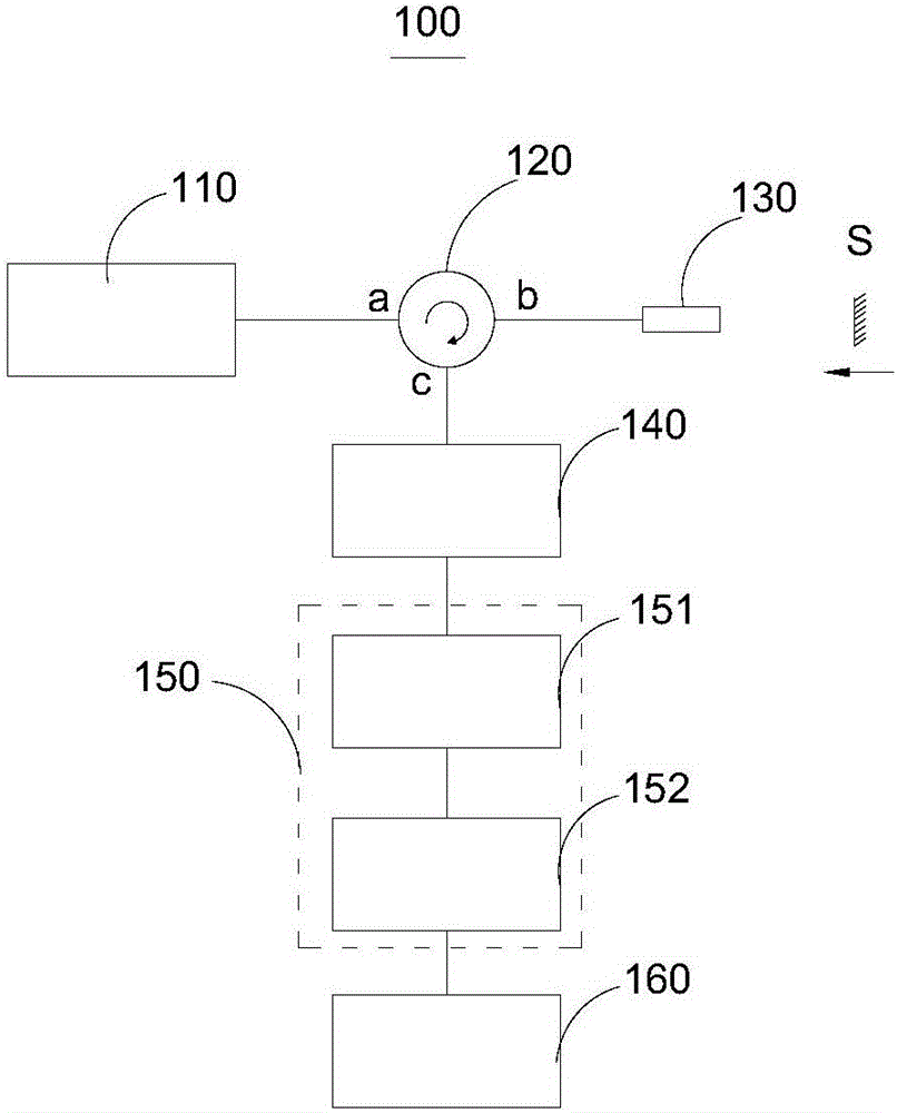
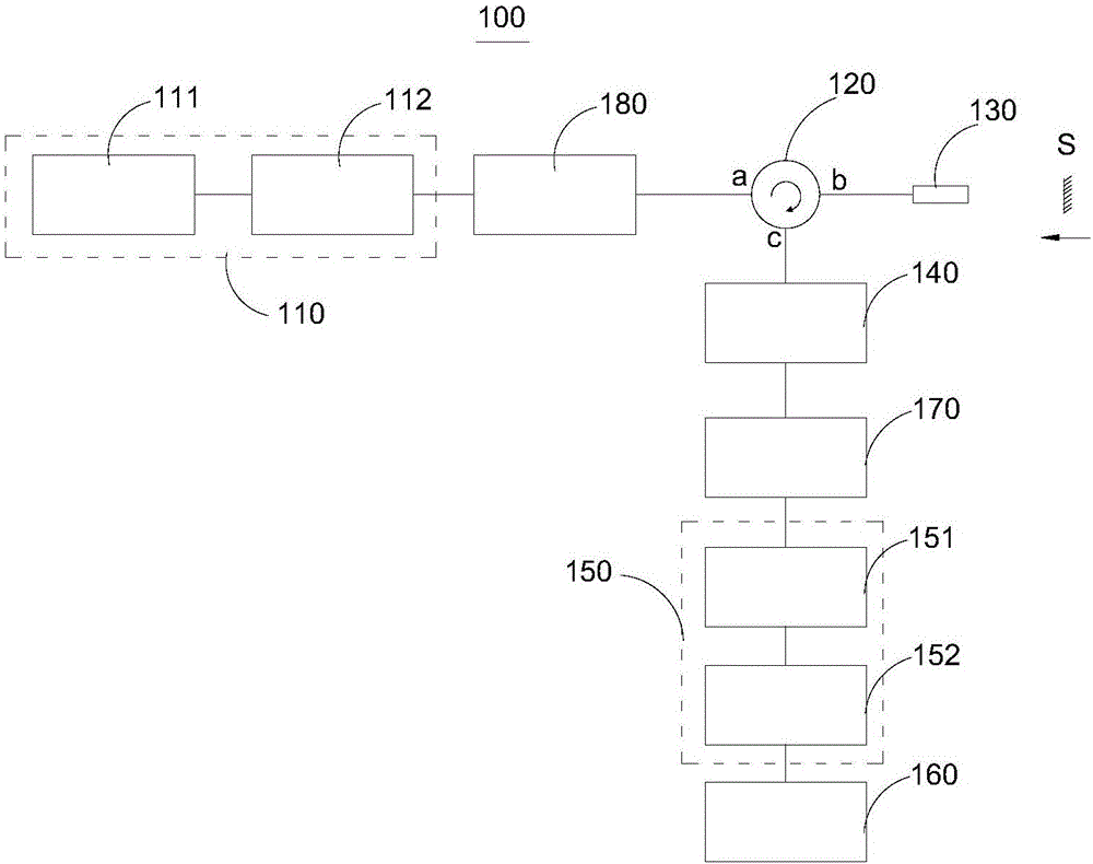
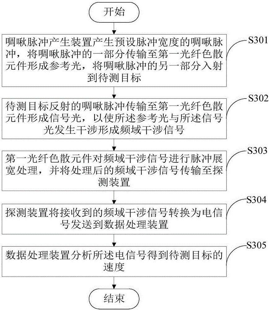
The invention provides an interference velocity measurement system and method, and belongs to the technical field of laser interference velocity measurement. The interference velocity measurement system comprises a chirped pulse generation device, a first optical fiber dispersion element, a detection device and a data processing device, and is characterized in that a part of chirped pulses with preset pulse width, which are generated by the chirped pulse generation device, is transmitted to the first optical fiber dispersion element so as to form reference light, and another part of the chirped pulses is incident on a target to be measured; chirped pulses reflected by the target to be measured are transmitted to the first optical fiber dispersion element so as to form signal light, frequency domain interference signals, which are formed by interference generated by the reference light and the signal light, are subjected to pulse broadening processing of the first optical fiber dispersion element and get into the detection device, and the detection device converts the frequency domain interference signals into electric signals and sends the electric signals to the data processing device. The interference velocity measurement system provided by the embodiment of the invention effectively reduces bandwidth requirements for the detection device used for recording the interference signals, and a time resolution and velocity measurement upper limit of the system is improved.

Description

technical field [0001] The present invention relates to the technical field of laser interference velocity measurement, in particular to an interference velocity measurement system and method. Background technique [0002] In the research of loading technologies such as explosives, laser devices, and electromagnetic drive devices, it is necessary to measure the speed at which the flyer is driven. Laser interferometric velocity measurement technology has the advantages of non-contact measurement, high time resolution, high velocity measurement accuracy and large measurement dynamic range, etc., and is widely used in the velocity measurement of shock waves, detonation waves and short-term high-speed moving objects. Therefore, the laser interferometric velocimetry technique is an important means to measure the moving speed of the flyer driven by laser or magnetic drive. Most of the existing laser interferometric speed measurement equipment uses photodetectors and oscilloscopes...

Claims


Application Information

Patent Timeline
Patent Type & Authority Applications(China)
IPC IPC(8): G01S17/58G01S7/481
CPCG01S7/4818G01S17/58
Inventor 刘寿先李建中陈光华陶世兴王竞彭其先邓向阳
Owner INST OF FLUID PHYSICS CHINA ACAD OF ENG PHYSICS
Why Eureka
Try Eureka