Photonic band-gap fiber based mode locked fiber laser at one micron

a fiber laser and mode lock technology, applied in the direction of laser details, basic electric elements, electrical equipment, etc., can solve the problems of difficult alignment maintenance, bulky laser systems, and inability to generate negative dispersions of conventional silica fibers

Inactive Publication Date: 2007-03-01
POLARONYX
View PDF6 Cites 7 Cited by
  • Summary
  • Abstract
  • Description
  • Claims
  • Application Information

AI Technical Summary

Benefits of technology

[0016] Another aspect of this invention is to provide a mode-locked fiber laser cavity with the PBF that for transmitting a laser projection with birefringence and with the polarization axis of the slow axis of one PM fiber port of the polarization beam splitter lined up with that of the PBF. The mode-locked fiber laser cavity further utilizes the SESAM to enhance a self-start in the mode-locked fiber laser cavity.

Problems solved by technology

Due to the nature of fiber materials, conventional silica fibers cannot generate negative dispersions.
Furthermore, when grating lens or prism pairs are implemented to correct the pulse shape distortions, such laser systems are often bulky, difficult for alignment maintenance, and also lack sufficient robustness.
All these difficulties prevent practical applications of the ultra-short high power lasers.
Historically, generation of mode-locked laser with the pulse width down to a femtosecond level is a difficult task due to limited resources of saturation absorbers and anomalous dispersions of fibers.
Conventionally, short pulse mode locked fiber lasers operated at wavelengths below 1.3 μm present a particular challenge is that there is no simple all fiber based solution for dispersion compensation in this wavelength regime.
Unfortunately these devices require the coupling of the fiber into a bulk device, which results in a laser that is highly sensitive to alignment and thus the environment
However, such configurations often developed into bulky and less robust systems due to the implementations of free space optics.
The limitations for practical application of such laser systems are even more pronounced due the pulse shape distortions when the pulse width is further reduced compounded with the requirement of high power fiber amplification.
When the pulse width narrows down to femtosecond level and the peak power increases to over 10 kW, strong nonlinear effects such as self phase modulation (SPM) and XPM will cause more serious spectral and temporal broadening.
These nonlinear effects and spectral and temporal broadening further causes a greater degree of distortions to the laser pulses.
The technical difficulties cannot be easily resolved even though a large mode area (LMA) fiber can be used to reduce SBS and SRS to increase saturation power.
However, the large mode area fiber when implemented will in turn cause a suppression of the peak power and leads to an undesirable results due to the reduction of the efficiency
For these reasons, the conventional technologies do not provide an effective system configuration and method to provide effective ultra-short pulse high power laser systems for generating high power laser pulses with acceptable pulse shapes.
In addition to the above described difficulties, these laser systems require grating pairs for dispersion control in the laser cavity.
Maintenance of alignment in such systems becomes a time consuming task thus prohibiting a system implemented with free space optics and grating pairs from practical applications.
Also, the grating pairs further add to the size and weight of the laser devices and hinder the effort to miniaturize the devices implemented with such laser sources.
However, since the conventional silica fibers cannot provide the required negative dispersions as that disclosed in these improved systems, a new and improved fiber that can generate negative dispersion is still required to overcome the above discussed difficulties and limitations.

Method used


Image

  • Photonic band-gap fiber based mode locked fiber laser at one micron
  • Photonic band-gap fiber based mode locked fiber laser at one micron

Examples


Embodiment Construction

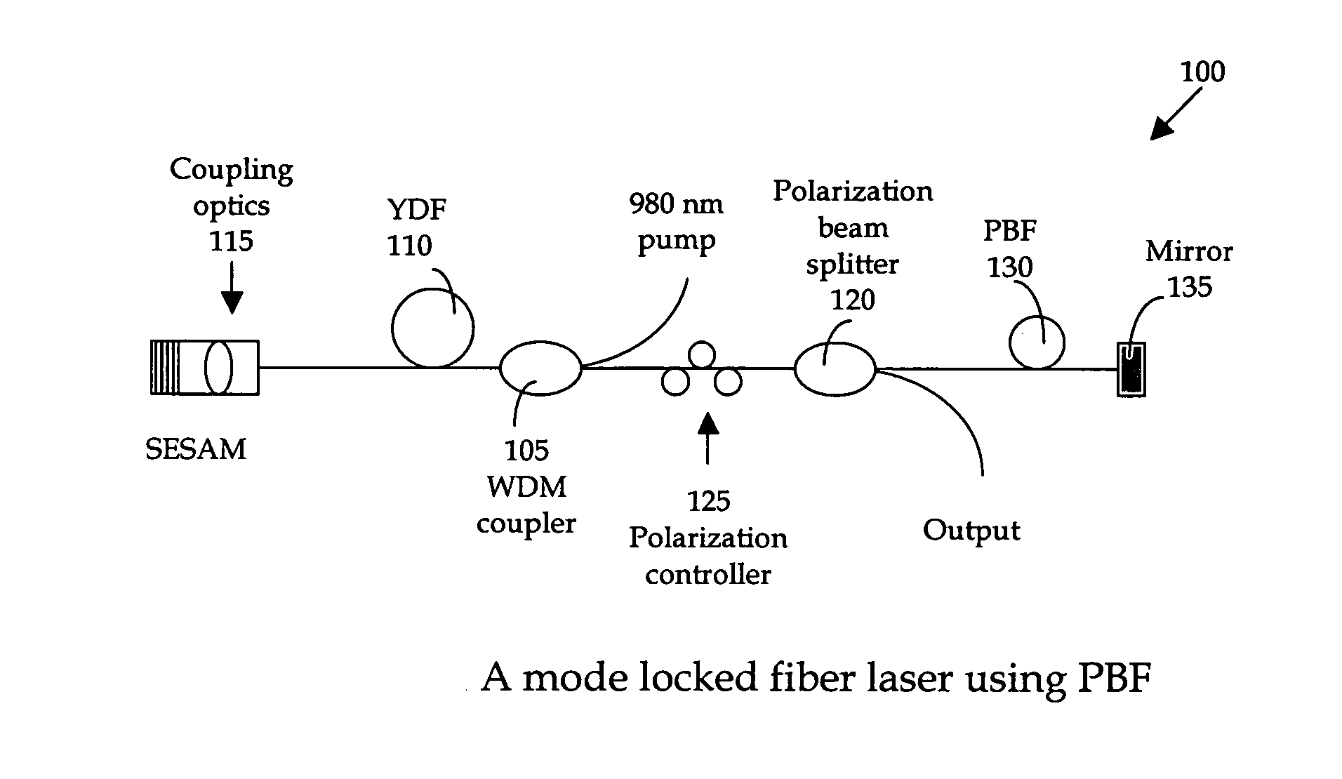
[0021] Referring to FIG. 1 for a schematic diagram of a nonlinear polarization pulse-shaping mode locked fiber laser 100 of this invention. The fiber laser system includes wavelength division multiplexing (WMD) coupler 105 to receive a laser input from a 980 nm pump for combining with a one micron signal to project to a gain medium Ytterbium (Yb) doped fiber (YDF) 110. An amplified laser signal is transmitted to a semiconductor saturation absorber (SESAM) 115 and to a polarization beam splitter 120 via a polarization controller 125. The polarization controller 125 is placed in front of the polarization beam splitter 120 for adjusting of the output coupling-ratio. The fiber laser system further includes a photonic band-gap fiber (PBF) 130 that includes a mirror 135 placed on one end-face of the PBF 130 to reflect the signal back into the cavity. The photonic band-gap fiber (PBF) 130 is a newly available fiber which dispersion can be manipulated to negative dispersion. The function of...


PUM


Abstract

A fiber laser cavity that includes a laser gain medium for receiving an optical input projection from a laser pump. The fiber laser cavity further includes a positive dispersion fiber segment and a negative dispersion fiber segment for generating a net negative dispersion for balancing a self-phase modulation (SPM) and a dispersion induced pulse broadening / compression in the fiber laser cavity for generating an output laser with a transform-limited pulse shape wherein the laser gain medium further amplifying and compacting a laser pulse. The gain medium further includes a Ytterbium doped fiber for amplifying and compacting a laser pulse. The fiber laser cavity further includes a polarization sensitive isolator and a polarization controller for further shaping the output laser.

Description

[0001] This Formal Application claims a Priority Date of Aug. 29, 2005 benefited from a Provisional Patent Application 60 / 713,650, 60 / 713,653, and 60 / 713,654 and a Priority Date of Sep. 1, 2005 benefited from Provisional Application 60 / 714,468 and 60 / 714,570 filed by one of the same Applicants of this Application.FIELD OF THE INVENTION [0002] The present invention relates generally to apparatuses and methods for providing short-pulsed mode-locked fiber laser. More particularly, this invention relates to new configurations and methods for providing a photonic band-gap fiber based mode-locked fiber laser BACKGROUND OF THE INVENTION [0003] Due to the nature of fiber materials, conventional silica fibers cannot generate negative dispersions. Therefore, a conventional fiber laser system configured by using the silica optical fibers must implement grating lens or prism pairs to generate negative dispersions. It is necessary to generate a negative dispersion in a fiber laser system for pro...

Claims


Application Information

Patent Timeline
Patent Type & Authority Applications(United States)
IPC IPC(8): H01S3/30H01S3/098
CPCH01S3/067H01S3/06725H01S3/1618H01S3/1118H01S3/06741
Inventor LIU, JIAN
Owner POLARONYX
Why Eureka
Try Eureka