Oil-water mixed cooling motor system and vehicle

A technology for cooling motors and oil-water mixing, applied in cooling/ventilation devices, electromechanical devices, electrical components, etc., can solve the problems of poor cooling effect, large space occupation, and high cost, so as to reduce costs, improve cooling effect, and reduce occupation effect of space

Active Publication Date: 2020-11-20
CHINA FIRST AUTOMOBILE
View PDF26 Cites 26 Cited by
  • Summary
  • Abstract
  • Description
  • Claims
  • Application Information

AI Technical Summary

Problems solved by technology

[0003] The traditional water-cooled motor cools the stator core by cooling the shell, but the end of the stator winding with severe heat dissipation cannot be directly cooled, and the heat of the winding can only be conducted to the shell through the air for cooling, and the cooling effect is poor
Most of the traditional oil-cooled motors only cool the ends of the stator windings, but cannot effectively cool the stator core and rotor magnetic steel. At the same time, traditional oil-cooled motors also need to add coolers to cool the oil, which is costly and takes up space. Big

Method used


Image

  • Oil-water mixed cooling motor system and vehicle
  • Oil-water mixed cooling motor system and vehicle
  • Oil-water mixed cooling motor system and vehicle

Examples


Embodiment Construction

[0063] In order to make the technical problems solved by the present invention, the technical solutions adopted and the technical effects achieved clearer, the technical solutions of the embodiments of the present invention will be further described in detail below in conjunction with the accompanying drawings. Obviously, the described embodiments are only the technical solutions of the present invention. Some, but not all, embodiments. Based on the embodiments of the present invention, all other embodiments obtained by those skilled in the art without making creative efforts belong to the protection scope of the present invention.

[0064] In the description of the present invention, it should be noted that the terms "center", "upper", "lower", "left", "right", "vertical", "horizontal", "inner", "outer" etc. The indicated orientation or positional relationship is based on the orientation or positional relationship shown in the drawings, and is only for the convenience of desc...


PUM


Abstract

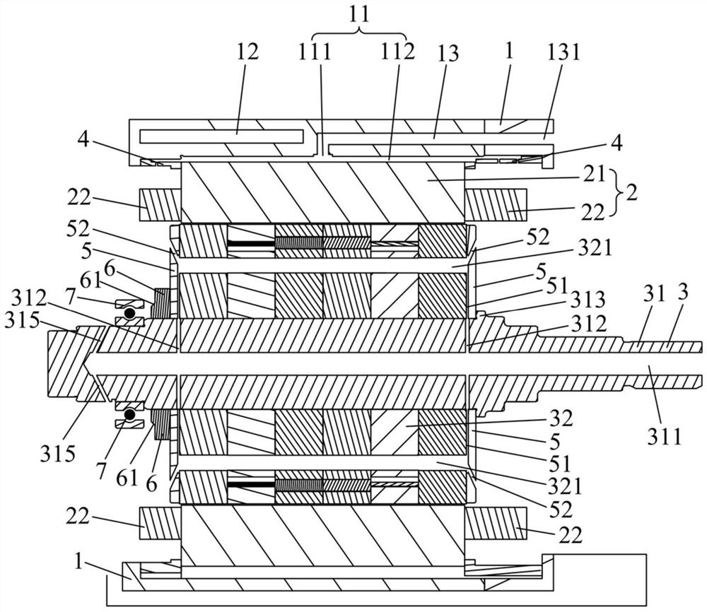
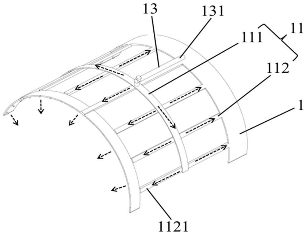
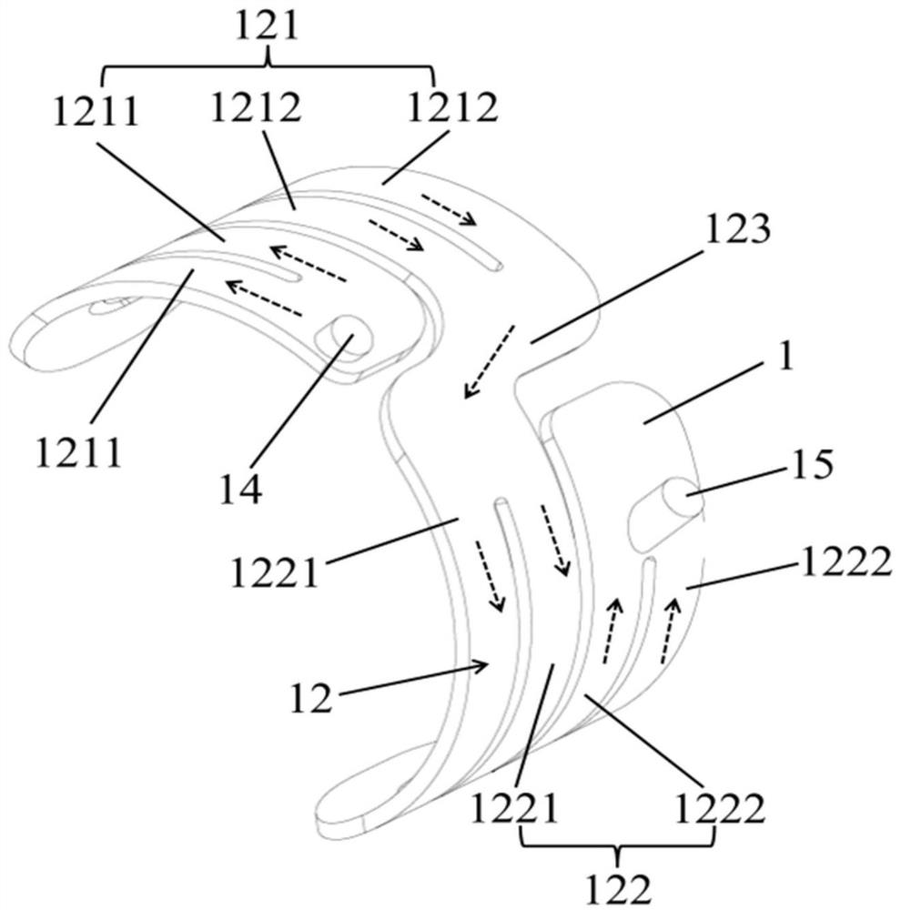
The invention belongs to the technical field of driving assemblies, and discloses an oil-water mixed cooling motor system and a vehicle. The motor system comprises a shell, a stator and a rotor; a first oil channel is formed in the shell and extends to a position between the shell and a stator core; an oil injection part is arranged on the inner side of the shell and located at the end of the stator core; and cooling oil can be at least injected to an end winding through an oil injection hole; a water channel is formed in the shell and is laminated with at least part of the first oil channel in a staggered manner; an oil guide piece is arranged on a rotor shaft and is positioned at the end part of a rotor core; a second oil channel comprises an oil inlet flow channel on the rotor shaft, amagnetic steel cooling flow channel between the rotor core and magnetic steel, an oil guide flow channel on the oil guide piece and a first oil throwing flow channel, wherein the oil guide flow channel is communicated with the oil inlet flow channel and the magnetic steel cooling flow channel; and cooling oil is at least thrown to the end winding through the first oil throwing flow channel. The vehicle comprises a motor system. According to the oil-water mixed cooling motor system and the vehicle of the invention, the stator core, the end winding and the magnetic steel are cooled at the same time; and the stator core and the end winding are cooled in a water-cooling and oil-cooling combined mode, so that a cooling effect is good.

Description

technical field [0001] The invention relates to the technical field of drive assembly, in particular to an oil-water mixing cooling motor system and a vehicle. Background technique [0002] With the rapid development of new energy vehicles, the electric drive system is also developing in the direction of high speed and high power, and the requirements for the motor cooling system are also getting higher and higher. [0003] The traditional water-cooled motor cools the stator core by cooling the shell, but the end of the stator winding that has serious heat dissipation cannot be directly cooled, and the heat of the winding can only be conducted to the shell through the air for cooling, and the cooling effect is poor. Most of the traditional oil-cooled motors only cool the ends of the stator windings, but cannot effectively cool the stator core and rotor magnetic steel. At the same time, traditional oil-cooled motors also need to add coolers to cool the oil, which is costly an...

Claims


Application Information

Patent Timeline
Patent Type & Authority Applications(China)
IPC IPC(8): H02K9/19H02K3/24H02K1/32H02K5/20H02K1/20
CPCH02K9/19H02K3/24H02K1/32H02K5/20H02K1/20
Inventor 高一赵慧超徐德才李全刘金锋文彦东张颖苍衍
Owner CHINA FIRST AUTOMOBILE
Why Eureka
Try Eureka