Piezoelectric inertia driven two-degree-of-freedom coupling retinal detachment feeding mechanism

A technology of retinal detachment and inertial drive, applied in ophthalmic surgery, etc., can solve problems such as easy to cause other symptoms, low success rate of surgery, easy hand tremor, etc., and achieve the effect of avoiding injury and high precision

Active Publication Date: 2020-11-24
HARBIN INST OF TECH
View PDF6 Cites 3 Cited by
  • Summary
  • Abstract
  • Description
  • Claims
  • Application Information

AI Technical Summary

Problems solved by technology

[0005] The present invention aims to solve the problems of low success rate of operation and easy to cause other symptoms in the existing manual use of tweezers to peel off the retina due to hand tremors during manual operation

Method used


Image

  • Piezoelectric inertia driven two-degree-of-freedom coupling retinal detachment feeding mechanism
  • Piezoelectric inertia driven two-degree-of-freedom coupling retinal detachment feeding mechanism
  • Piezoelectric inertia driven two-degree-of-freedom coupling retinal detachment feeding mechanism

Examples


specific Embodiment approach 1

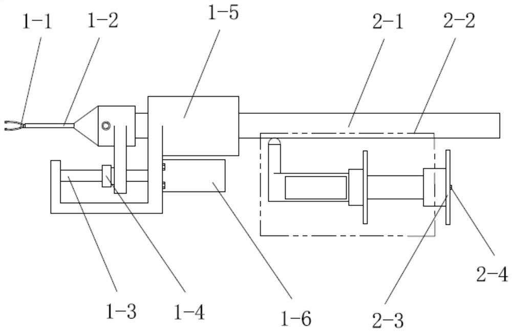
[0018] Specific implementation mode one: combine Figure 1 to Figure 3 To illustrate this embodiment, a piezoelectric inertia-driven two-degree-of-freedom coupled retinal peeling feed mechanism includes a retina clamping module and a driving module, and the driving module includes a motion axis 2-1 and a two-degree-of-freedom coupled piezoelectric inertial motor 2- 2. Piezoelectric stacking base 2-3 and rolling ball plunger 2-4. The retinal clamping module is arranged horizontally. The retinal clamping module includes tweezers 1-1, outer tube assembly 1-2, lead screw 1-3, and nuts 1-4. Connect the fixing part 1-5 and the stepping motor 1-6, the stepping motor 1-6 is installed horizontally on the connecting fixing part 1-5, and the lead screw 1-3 is horizontally installed on the connecting fixing part 1-5 , and the lead screw 1-3 is connected with the output shaft of the stepper motor 1-6, the nut 1-4 is installed on the lead screw 1-3, the outer tube assembly 1-2 is installed ...

specific Embodiment approach 2

[0022] Specific implementation mode two: combination figure 1 Describe this embodiment, the retina clamping module of this embodiment includes tweezers 1-1, outer tube assembly 1-2, lead screw 1-3, nut 1-4, connecting fixture 1-5 and stepper motor 1-6 , the stepper motor 1-6 is horizontally installed on the connecting fixture 1-5, the lead screw 1-3 is horizontally installed on the connecting fixture 1-5, and the output shaft of the lead screw 1-3 and the stepping motor 1-6 Connection, the nut 1-4 is installed on the lead screw 1-3, the outer tube assembly 1-2 is installed on the lead screw 1-3 and moves horizontally on the lead screw 1-3, the tweezers 1-1 is installed horizontally on the outer tube assembly 1 -2 within. With such arrangement, it is convenient to quickly and flexibly adjust the protruding position of the tweezers. Other compositions and connections are the same as in the first embodiment.

[0023] The outer tube assembly 1-2 of this embodiment is composed o...

specific Embodiment approach 3

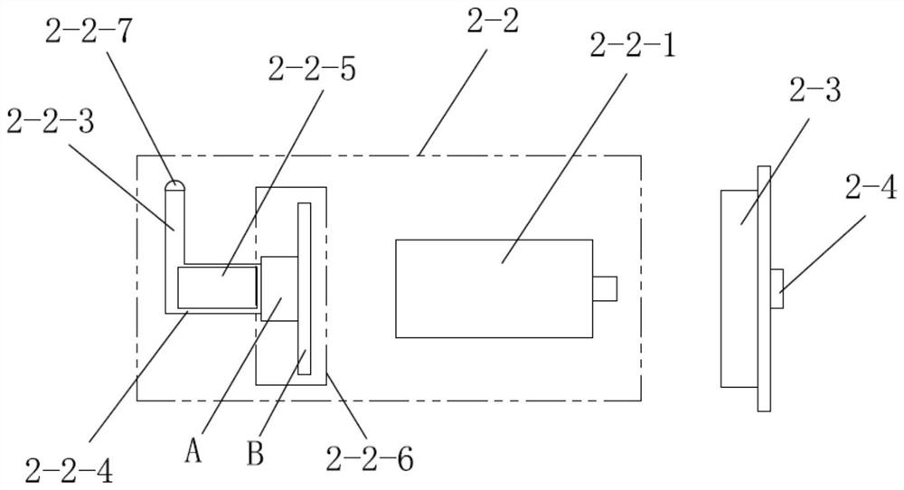
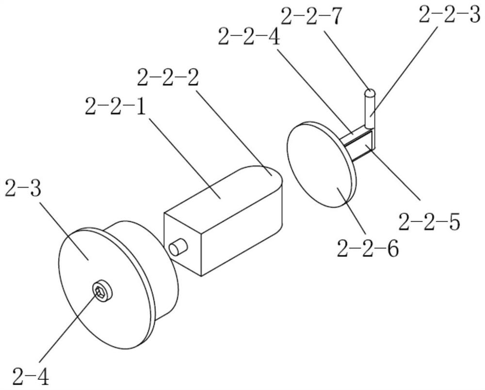
[0024] Specific implementation mode three: combination Figure 1 to Figure 3 Describe this embodiment, the two-degree-of-freedom coupled piezoelectric inertia motor 2-2 of this embodiment includes a piezoelectric stack 2-2-1, a stainless steel ball head 2-2-2 and a flexible beam assembly, and the piezoelectric stack 2-2 One end of -1 is provided with a boss, and the rolling ball head plunger 2-4 is set on the boss, and the other end of the piezoelectric stack 2-2-1 is provided with a stainless steel ball head 2-2-2, a stainless steel ball The front end of the head 2-2-2 is installed with a flexible beam assembly. So set, the rolling ball plunger 2-4 is used to adjust the initial pressure of the piezoelectric stack and the flexible beam base. The stainless steel ball head 2-2-2 is pasted on the piezoelectric stack to prevent the piezoelectric stack from being damaged during expansion and contraction. Other compositions and connections are the same as those in Embodiment 1 or ...


PUM


Abstract

The invention provides a piezoelectric inertia driven two-degree-of-freedom coupling retinal detachment feeding mechanism, and relates to a retinal detachment feeding mechanism. The problems that in an existing process of manually detaching the retina with tweezers, due to the fact that the hands of people are prone to shaking during manual operation, the operation success rate is low, and other symptoms are prone to being caused are solved. A moving shaft is coaxial and connected with the root of the tweezers of a retina clamping module, a base is installed under the moving shaft, a two-degree-of-freedom coupling piezoelectric inertia motor is installed on the base, and the two-degree-of-freedom coupling piezoelectric inertia motor drives the moving shaft to linearly feed and rotate around the axis. The purpose of controlling the tweezers to be opened and closed is achieved by controlling an outer pipe to move front and back in the axial direction through a stepping motor, and when the outer pipe moves forwards, the outer pipe extrudes the tweezers to close the tweezers. When the outer pipe moves backwards, the tweezers are released and automatically opened. The mechanism is usedfor retinal detachment feeding of an ophthalmic surgery robot.

Description

technical field [0001] The invention relates to a retinal peeling feeding mechanism, in particular to a piezoelectric inertia-driven two-degree-of-freedom coupling retinal peeling feeding mechanism. Background technique [0002] Peeling off the outermost external membrane from the retina is already a canonical vitreoretinal procedure. During the procedure, the surgeon first uses a pick to pick out the edges on the membrane, then uses forceps to lift and peel off the membrane. Due to the poor visibility of the external membrane (translucent and very thin), the tissue characteristics of different parts are different, and the current operation is very difficult. [0003] In addition, hand tremors, fatigue caused by long-term surgery, and lack of force feedback (the contact force is much smaller than the human perception limit) must be taken into account, which will further reduce the success rate of surgery. Therefore, it is very difficult for surgeons without extensive surgi...

Claims


Application Information

Patent Timeline
Patent Type & Authority Applications(China)
IPC IPC(8): A61F9/007
CPCA61F9/007A61F9/00736A61F9/00763
Inventor 张赫易浩然赵杰
Owner HARBIN INST OF TECH
Why Eureka
Try Eureka