Gear grinding fixture for bevel gear

A gear and tooth grinding technology, which is applied to gear tooth manufacturing devices, components with teeth, belts/chains/gears, etc., can solve problems such as deformation of rigid positioning shafts and out-of-tolerance accumulative Fp of peripheral pitches, etc., to ensure rigidity, Guarantee the accuracy and eliminate the effect of random out-of-tolerance products

Active Publication Date: 2020-11-24
东风汽车零部件集团有限公司刃量具分公司
View PDF9 Cites 3 Cited by
  • Summary
  • Abstract
  • Description
  • Claims
  • Application Information

AI Technical Summary

Problems solved by technology

See previous fixtures on KAPP figure 2 , because the d/d1 of the processed gear is greater than 4, because the fixture does not have enough rigidity, the positioning axis may be deformed when the KAPP machine tool applies pressure. The actual measurement: P1 jumps about

Method used


Image

  • Gear grinding fixture for bevel gear
  • Gear grinding fixture for bevel gear
  • Gear grinding fixture for bevel gear

Examples


Embodiment Construction

[0027] pass below Figure 3 ~ Figure 7b As well as listing some optional embodiments of the present invention, the technical solutions (including preferred technical solutions) of the present invention are further described in detail. Apparently, the described embodiments are only some of the embodiments of the present invention, not all of them. Based on the embodiments of the present invention, all other embodiments obtained by persons of ordinary skill in the art without creative efforts fall within the protection scope of the present invention.

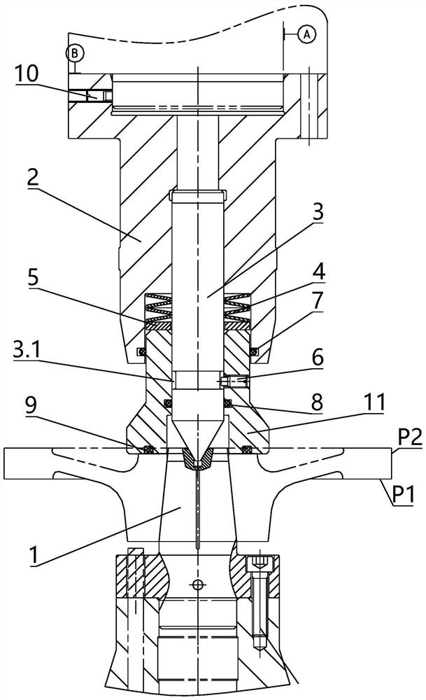
[0028] Such as image 3 and Figure 5 As shown, the gear grinding fixture of the tapered hole gear designed by the present invention is divided into a positioning shaft 1 and a pressing part, a top seat 2, a top 3, a butterfly spring 4, an adjusting washer 5, a limit screw 6, a first seal Ring 7, second sealing ring 8, rubber washer 9, three adjustment screws 10, and upper pressure head 11 form the pressing part. The pressing ...


PUM


Abstract

The invention discloses a gear grinding fixture for a bevel gear. The gear grinding fixture comprises a positioning shaft connected with a fixed part of a machine tool and a center seat connected witha movable part of the machine tool. The center seat is provided with a center and an upper indenter coaxial with the center seat. One end of the upper indenter is located in the center seat, and theother end extends out of the center seat and the end face can abut against a gear to be processed. A spring is arranged between the top surface of the upper indenter and the center seat. One end of the center is located in the center seat. The other end of the center penetrates from the spring and the upper indenter and the contact surface between the end and a central hole of the positioning shaft is a cone surface. The top of the cone surface is a flat surface and the flat surface is flush with the end surface of the upper indenter. The gear grinding fixture eliminates the random out-of-tolerance phenomenon of products during gear grinding and satisfies the requirements of gear grinding.

Description

technical field [0001] The invention belongs to the technical field of processing fixtures, in particular to a gear grinding fixture for thin disc gears whose ratio of the pitch circle diameter of the gear to the large end size of a mounting taper hole is greater than 4. Background technique [0002] Grinding on a KAPP gear grinding machine such as figure 1 The gear shown (gear accuracy is DIN 7), positioned with a tapered hole (α), and pressed with K face. See previous fixtures on KAPP figure 2 , because the d / d1 of the processed gear is greater than 4, because the fixture does not have enough rigidity, the positioning axis may be deformed when the KAPP machine tool applies pressure. The actual measurement: P1 jumps about 0.003mm before pressing, and P2 jumps about 0.005mm. After pressing, the jump of P1 is about 0.05mm, and the jump of P2 is about 0.025mm, which will cause the cumulative pitch Fp of the processed gear and the runout Fr of the ring gear to be out of tole...

Claims


Application Information

Patent Timeline
IPC IPC(8): B23F23/06
CPCB23F23/06
Inventor 冯乾新张瑾王香丽陈亮
Owner 东风汽车零部件集团有限公司刃量具分公司
Why Eureka
Try Eureka