Steel reinforcement cage welding device and welding method

A technology for welding equipment and steel cages, applied in welding equipment, welding equipment, auxiliary welding equipment, etc., can solve the problems of large size, inconvenient transportation of steel cages, and high transportation costs

Pending Publication Date: 2020-11-24
浙江坤德创新岩土工程有限公司
View PDF0 Cites 4 Cited by
  • Summary
  • Abstract
  • Description
  • Claims
  • Application Information

AI Technical Summary

Problems solved by technology

[0002] The existing steel cage production equipment is generally large in size and can only be used in the factory, and then the welded steel cage is transported to the designated place, but the steel cage is inconvenient to transport, and its transportation cost is also high
At present, most of the steel cages produced on the project site are manually welded, and the quality is uneven, which has a great impact on the quality and safety of the project.
At the same time, the efficiency of manual welding is low, and the cost of manpower and materials is high.

Method used


Image

  • Steel reinforcement cage welding device and welding method
  • Steel reinforcement cage welding device and welding method
  • Steel reinforcement cage welding device and welding method

Examples


Embodiment 1

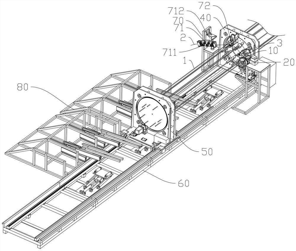
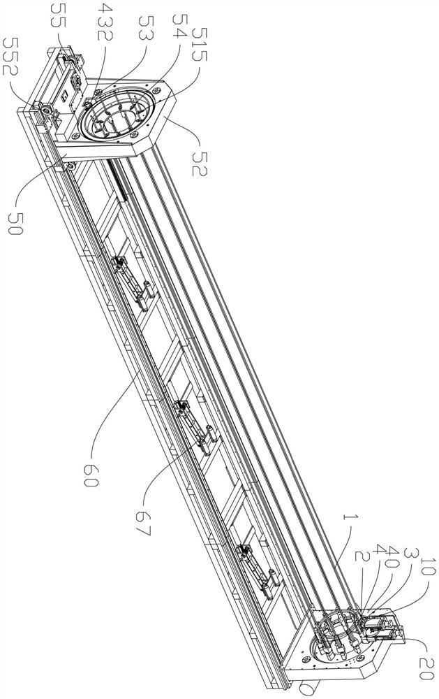
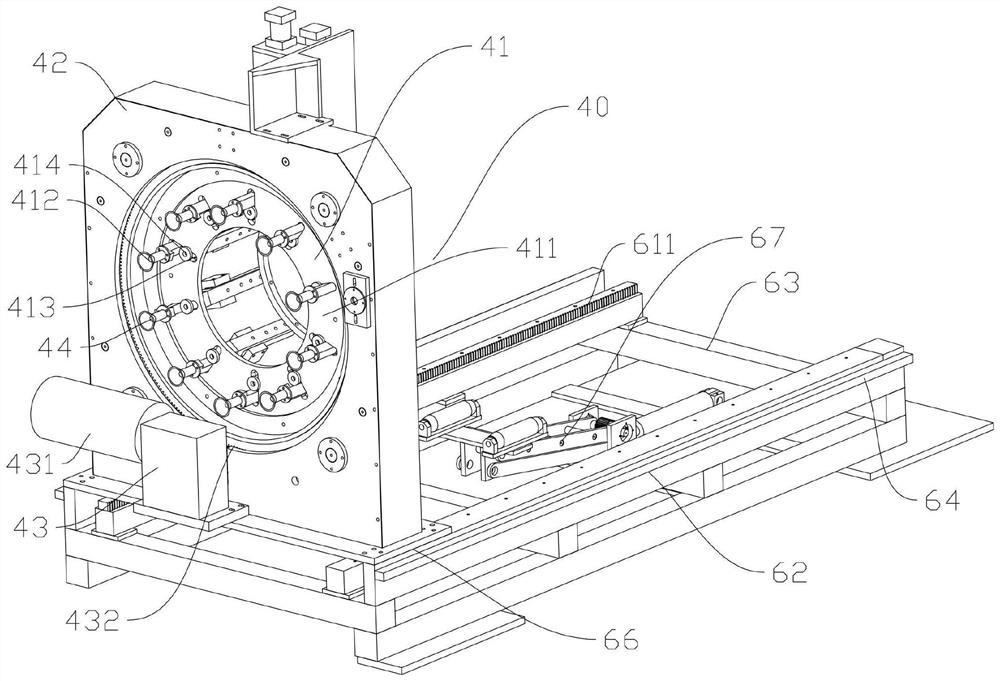
[0068] When starting welding, the first electrode conductor 12 is driven by the first electrode moving part 11, approaches the welding position 3, and then reaches the welding position 3. At this time, the first electrode conductor 12 is driven by the first electrode moving part 11 Continue to move downwards, so as to squeeze and apply force to the intersection point 4, the first electrode conductor 12 is in a energized state, and forms a loop with the intersection point 4 and the second electrode conductor 22, and the intersection point 4 is heated and squeezed to apply force , so that the first rib body 1 and the second rib body 2 are welded at the intersection point 4; then, the first electrode conductor 12 leaves the welding position 3 under the action of the first electrode moving part 11, and does not connect with the first rib body 1 is in contact with the second rib body 2, the first rib body 1 and the second rib body 2 move relatively, and form the next intersection po...

Embodiment 2

[0070]When starting welding, the first electrode conductor 12 is driven by the first electrode moving part 11, approaches the welding position 3, then reaches the welding position 3, and stays at the welding position 3 under the action of the first electrode moving part 11, when The first rib body 1 and the second rib body 2 meet at the welding position 3 to form a junction point 4. The first electrode conductor 12 stays at the welding position 3 and keeps in contact with the junction point 4, and can pass through the first electrode moving part 11 Make the first electrode conductor 12 maintain the position but squeeze and apply force to the junction 4, the first electrode conductor 12 is in a energized state, forms a loop with the junction 4 and the second electrode conductor 22, the junction 4 is heated, and Extruded and applied force, so that the first rib body 1 and the second rib body 2 are welded at the intersection point 4; then, the force imparted by the first electrode...


PUM


Abstract

The invention discloses a steel reinforcement cage welding device and a welding method. The welding device comprises a first reinforcement body assembly part, a welding device and a guide rail, wherein a fixed assembly module and a movable assembly module comprise rotating modules for driving first reinforcement bodies to synchronously rotate; welding positions are intersections of the first reinforcement bodies and second reinforcement bodies; and first electrodes, second electrodes and the intersections of the first reinforcement bodies and the second reinforcement bodies form electric conducting loops for welding and fixing the second reinforcement bodies with the first reinforcement bodies. The welding device has the following advantages: the first electrodes and the second electrodesin the welding device form the electric conducting loops, so that welding points of the first reinforcement bodies and the second reinforcement bodies are firmer; and the welding method adopting the device can greatly improve the welding efficiency, and can improve the welding quality of steel reinforcement cages.

Description

technical field [0001] The invention relates to the technical field of building reinforcement processing, in particular to a reinforcement cage welding equipment and a welding method. Background technique [0002] The existing steel cage production equipment is generally large in size and can only be used in factories, and then the welded steel cages are transported to designated places, but the steel cages are relatively inconvenient to transport, and their transportation costs are also high. At present, most of the steel cages produced on the project site are manually welded, and the quality is uneven, which has a great impact on the quality and safety of the project. At the same time, the efficiency of manual welding is low, and the cost of manpower and materials invested is relatively high. Contents of the invention [0003] In order to overcome the deficiencies of the prior art, one of the objects of the present invention is to provide a steel cage welding equipment,...

Claims


Application Information

Patent Timeline
IPC IPC(8): B23K37/04B23K37/047B23K11/36B21F27/20
CPCB21F27/20B23K11/36B23K37/0443B23K37/047
Inventor 陈天雄朱国强张楚福吕美东
Owner 浙江坤德创新岩土工程有限公司
Why Eureka
Try Eureka