Check patentability & draft patents in minutes with Patsnap Eureka AI!

A CNC machining center with automatic loading and unloading and its automatic loading and unloading method

An automatic loading and unloading and processing center technology, applied in stone processing equipment, stone processing tools, metal processing equipment, etc., can solve the problems of long auxiliary time for refueling, labor intensity and labor hazards, and large machine tools, etc. Safety and refueling efficiency, improved controllability, and strong scalability

Active Publication Date: 2022-05-06
江西衡源智能装备股份有限公司
View PDF9 Cites 0 Cited by
  • Summary
  • Abstract
  • Description
  • Claims
  • Application Information

AI Technical Summary

Problems solved by technology

At present, single-station or double-station milling machine tools are widely used in the market. The pick-and-place of processing materials is generally done manually, and the production efficiency is low.
Manual refueling, the production cycle of a single piece is short, requires a lot of labor, low productivity, prone to work-related injuries, high labor intensity and labor hazards
At present, when the grinding and milling machines on the market perform automatic refueling, the next billet and finished material are often discharged through a single retrieving end. Therefore, it is often necessary to temporarily suspend the entire machine tool processing to perform refueling. Therefore, it is necessary It takes a long time to take and change materials, and generally the material racks are fixed on the mobile workbench or inside the machine tool close to the front end of the workbench, which requires a large working space inside the machine tool, and the operator is very far away from the processing area of ​​the equipment. The rack is placed inside the machine tool, resulting in a very large machine tool, and it is very troublesome to replace the rack

Method used


Image

  • A CNC machining center with automatic loading and unloading and its automatic loading and unloading method
  • A CNC machining center with automatic loading and unloading and its automatic loading and unloading method

Examples


Embodiment Construction

[0043] The specific implementation manners of the present invention will be further described in detail below in conjunction with the accompanying drawings and embodiments. The following examples are used to illustrate the present invention, but are not intended to limit the scope of the present invention.

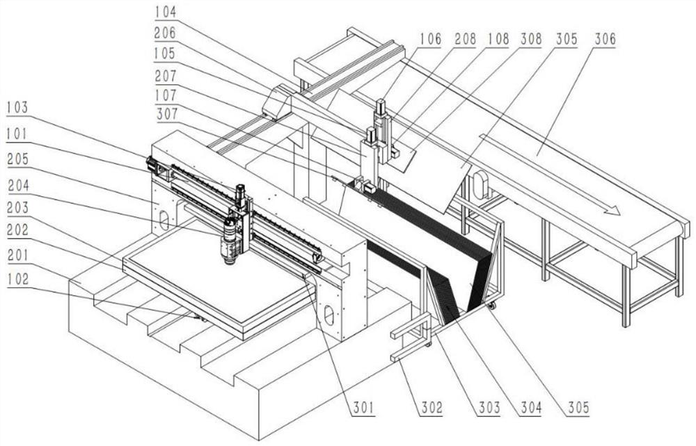
[0044] Such as figure 1 As shown in the figure, the CNC machining center with automatic loading and unloading provided by the present invention includes a CNC machine tool, a multi-terminal automatic reloading device and a rack device with a blank pick-and-place end and a finished product pick-and-place end;

[0045] The material rack device 303 is set independently of the CNC machine tool, and is located behind the CNC machine tool, in accordance with the direction shown in the figure.

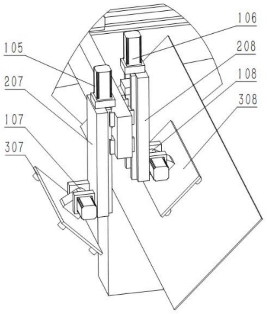
[0046] The multi-terminal automatic refueling device is erected on the machine bed of the numerically controlled machine tool, and moves back and forth relative to the machine bed. The ...


PUM


Abstract

The invention provides a numerically controlled machining center with automatic loading and unloading (hereinafter referred to as a machining center) and an automatic loading and unloading method thereof. The machining center includes a CNC machine tool with a processing platform on the machine bed, and also includes a multi-terminal automatic refueling device and a material rack device; the material rack device is set independently of the CNC machine tool; the multi-terminal automatic reloading device is erected on the machine bed, And it includes the billet pick-and-place end and the finished product pick-and-place end that can reciprocate between the material change position and the upper and lower material levels of the rack device. The loading of the next blank and the unloading of the finished material to the magazine device. The machining center of the present invention can pick and place blanks and finished materials at the same time, which improves the continuity of picking and changing materials. It is not necessary to stop the machining of the machine tool when the finished material is unloaded and the next blank is loaded, which improves the operating efficiency of the machine tool, and It reduces the occupation of the internal space of the machine bed, and is especially suitable for processing large-size plates.

Description

technical field [0001] The invention relates to the technical field of plate numerical control processing, in particular to a numerical control machining center with automatic loading and unloading and an automatic loading and unloading method thereof. Background technique [0002] At present, the forming process of special-shaped glass panels adopts water cutting or ordinary profiling grinding. Single-station or double-station grinding and milling machines are commonly used in the market at present, and the pick-and-place of the material during processing is generally carried out manually, and the production efficiency is low. Manual refueling, the production cycle of a single piece is short, requires a lot of labor, low productivity, prone to work-related injuries, high labor intensity and labor hazards. At present, when the grinding and milling machines on the market perform automatic refueling, the next billet and finished material are often discharged through a single ...

Claims


Application Information

Patent Timeline
Patent Type & Authority Patents(China)
IPC IPC(8): B24B7/24B24B41/00B24B55/06B24C1/04B24C3/02B24C9/00B28D1/18B28D7/00B28D7/02
CPCB24B7/24B24B41/005B24B55/06B28D1/18B28D7/005B28D7/00B28D7/02B24C1/045B24C3/02B24C9/00
Inventor 陈林王焱李林
Owner 江西衡源智能装备股份有限公司
Features
  • R&D
  • Intellectual Property
  • Life Sciences
  • Materials
  • Tech Scout
  • Unparalleled Data Quality
  • Higher Quality Content
  • 60% Fewer Hallucinations
Learn More