
A workpiece transport device

A technology for workpiece transportation and equipment, which is applied in metal processing equipment, grinding workpiece support, grinding/polishing equipment, etc., can solve the problems of workpiece processing efficiency, single structure and function of cart, and processing, so as to facilitate maintenance and reduce Processing time and the effect of improving processing efficiency

Active Publication Date: 2021-10-08
孟豹
View PDF11 Cites 0 Cited by
  • Summary
  • Abstract
  • Description
  • Claims
  • Application Information

AI Technical Summary

Problems solved by technology

The rough parts are generally transported to processing equipment such as grinding equipment by cart. The cart mainly includes a car body and rollers installed at the bottom of the car body. There is a push handle on the car body. The operator loads the blank into the car body Then push the cart to the processing equipment such as grinding equipment through the push handle. Therefore, the existing cart has a single structure and function. During the transportation process, the cart cannot process the workpiece, that is, it has little impact on the processing efficiency of the workpiece.

Method used


Image

  • A workpiece transport device
  • A workpiece transport device
  • A workpiece transport device

Examples


Embodiment 1

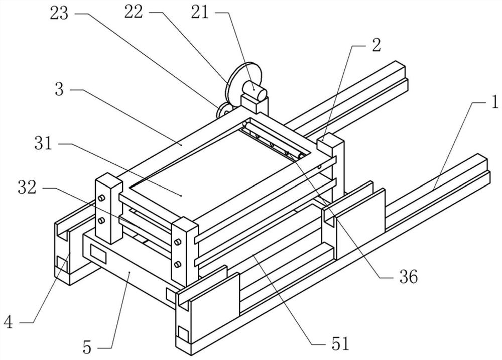
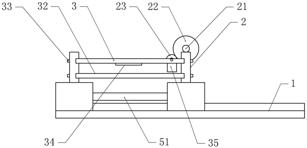
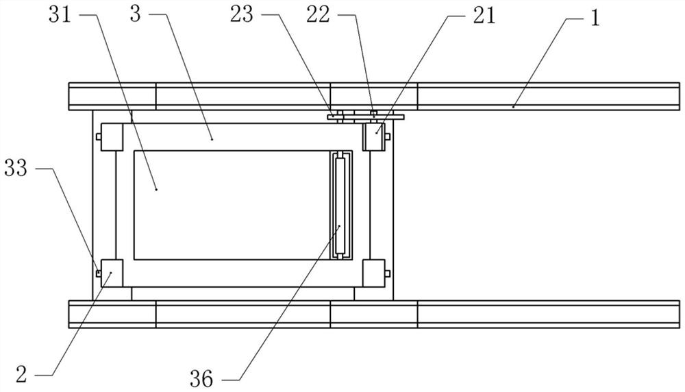
[0039] Basic as attached figure 1 And attached figure 2 As shown, a workpiece transportation device includes two guide rails 1, and the guide rails 1 are fastened to the ground by bolts. The top of the guide rail 1 is provided with a vehicle frame 5, on which the bolts are fixed with a reinforcement shaft 51, and both sides of the vehicle frame 5 are fixed with guide blocks 4 by bolts, the number of guide blocks 4 on each side of the vehicle frame 5 in this embodiment There are two guide blocks 4 on both sides that are horizontally slidably connected to the guide rail 1.

[0040] as attached image 3 , attached Figure 4 , attached Figure 5 And attached Image 6 As shown, two support shafts 2 are fixed with bolts on both sides of the support shaft 2, and the side of the support shaft 2 facing the middle of the vehicle frame 5 is provided with a number of draw-in slots, and the inner threads of the draw-in slots are connected with fasteners 33. The fastener 33 is a bolt...

Embodiment 2

[0048] The difference between embodiment two and embodiment one is that, as attached Figure 7 As shown, the left side of the vehicle frame 5 has a cavity, and a pressure plate 52 is vertically slidably connected in the cavity, and the upper end of the pressure plate 52 is hinged with a connecting rod. The connecting rod and the main gear 22 constitute a slider crank mechanism.

[0049] The pressure plate 52 separates the cavity into an upper chamber and a lower chamber. The lower chamber communicates with a first air intake check valve 58 fixed on the vehicle frame 5 by screws. The first air intake check valve 58 communicates with an air pipe 57. The air pipe 57 and The pipe fitting 35 communicates, and the lower chamber communicates with the first air outlet one-way valve 53, the first air outlet one-way valve 53 communicates with the outside air, and the inner side wall of the lower chamber is fixed with a filter screen for filtering the first air outlet one-way valve 53 ....


PUM


Abstract

The invention relates to the technical field of workpiece transportation, and discloses a workpiece transportation device, comprising a vehicle frame and a support shaft fixed on the vehicle frame, wherein several placement groups are arranged on the support shaft; the placement plate comprises an upper plate and a lower plate, the upper plate and the The lower plate and the supporting shaft can be detachably connected, the upper plate is provided with an inclined upper placement slot, and the lower plate is provided with an inclined lower placement slot, the upper placement slot and the lower placement slot are inclined in opposite directions, and the lower end of the upper placement slot is A pipe fitting connecting the upper plate and the lower plate is arranged between the upper end of the lower placing slot and the upper plate; the upper part of the pipe fitting is provided with a grinding roller which is rotatably connected with the upper plate, the grinding roller is coaxially fixed with a slave gear, and the supporting shaft is fixed with a driving member. A main gear meshed with the slave gear is fixed coaxially on the output shaft of the driving element. The invention has a simple structure, and can perform preliminary processing and grinding on the workpiece during transportation, thereby improving the efficiency of the workpiece during processing by grinding equipment.

Description

technical field [0001] The invention relates to the technical field of workpiece transportation, in particular to workpiece transportation equipment. Background technique [0002] The workpiece refers to the processing object in the machining process. It can be a single part or a combination of several parts fixed together. The processing methods of the workpiece are various, such as turning, milling, planing, grinding, casting, forging, etc. The processing procedure of the workpiece also varies with the processing method. change with change. [0003] Under normal circumstances, the initial state of the workpiece is a blank, and the blank is processed into a formed workpiece after grinding and other processes. The rough parts are generally transported to processing equipment such as grinding equipment by cart. The cart mainly includes a car body and rollers installed at the bottom of the car body. Push handles are installed on the car body. The operator loads the blank int...

Claims


Application Information

Patent Timeline
Patent Type & Authority Patents(China)
IPC IPC(8): B24B19/00B24B41/00B24B41/04B24B41/06B24B47/20B24B55/06
CPCB24B19/00B24B41/005B24B41/04B24B41/06B24B47/20B24B55/06
Inventor 孟豹
Owner 孟豹
Learn More