Riverway sludge treatment system and method

A river sludge and treatment system technology, applied in sludge treatment, water/sludge/sewage treatment, dehydration/drying/thickened sludge treatment, etc., can solve the problem of small space on the dredging ship site and achieve the purpose of preventing sediment Settlement, the effect of ensuring stability

Pending Publication Date: 2020-11-24
江苏碧诺环保科技有限公司
View PDF0 Cites 1 Cited by
  • Summary
  • Abstract
  • Description
  • Claims
  • Application Information

AI Technical Summary

Problems solved by technology

[0005] The innovation of the present invention is that the dredging ship in the present invention can solve the problems of narrow site space and long-distance transportation, and can completely separate the water and mud in the silt

Method used


Image

  • Riverway sludge treatment system and method
  • Riverway sludge treatment system and method

Examples


Embodiment 1

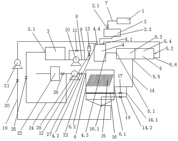
[0023] Embodiment 1: as figure 1 As shown, a river channel sludge treatment system includes a dredging ship 1, a grid machine 2, a dosing device 3, a mixing tank 4, a solid-liquid separator 5, a sedimentation tank 6, and the output pipe 7 of the dredging ship 1 is connected to the grid The material inlet 2.1 of the grid machine, the material outlet 2.2 of the grid machine are connected to the material inlet 4.1 of the mixing tank, the dosing device 3 is connected to the dosing port 4.2 of the mixing tank through the dosing pipe 8, and the dosing pipe 8 is provided with a dosing return pipe 9, The dosing pipe 8 is provided with a dosing pump 10, the dosing return pipe 9 is connected to both ends of the dosing pump 10, the dosing return pipe 9 is provided with a No. 4 valve 11, the dosing return pipe 9 and the dosing pipe 8 No. 5 valve 12 and flowmeter 13 are arranged in turn on the dosing pipe 8 at the dosing port 4.2 of the mixing tank between the connecting points, the materi...

Embodiment 2

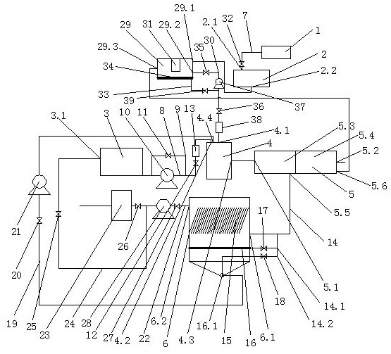
[0024] Embodiment 2: as figure 2As shown, a river channel sludge treatment system includes a dredging ship 1, a grid machine 2, a dosing device 3, a mixing tank 4, a solid-liquid separator 5, a sedimentation tank 6, and the output pipe 7 of the dredging ship 1 is connected to the grid The grid machine material inlet 2.1, a buffer tank 29 is arranged between the grid machine 2 and the mixing tank 4, the grid machine material outlet 2.2 is connected with the buffer tank material inlet 29.1, and the buffer tank material outlet 29.2 passes through the second pipeline 30 and the mixing tank material The inlet 4.1 is connected; the buffer tank 29 is provided with a liquid level gauge 31, and the output pipe 7 is provided with an output valve 32; the solid-liquid separator 5 is a multi-stage elliptical stacked solid-liquid separator 5, and the solid-liquid separator 5 separates the solid-liquid The two sections from the machine material inlet 5.1 to the sludge outlet 5.2 of the soli...

Embodiment 3

[0025] Embodiment 3: A river channel sludge treatment method, the river channel sludge is transported to the grid machine 2, and the sludge intercepted by the grid machine 2 enters the mixing tank 4; in the mixing tank 4, the flocculation agent is added through the dosing device 3 to flocculate Coagulation of chemicals and sludge; after coagulation, it enters the solid-liquid separator 5 for separation, and the separation is divided into two stages. The first stage is the concentration section 5.3, and the second stage is the pressing section 5.4. The concentrated water in the concentration section 5.3 passes through the sedimentation tank 6 for precipitation After discharge, the squeezed water in the squeezing section 5.4 flows back to the mixing tank 4 for further separation, and the mud cake separated by the solid-liquid separator 5 is discharged.


PUM


Abstract

The invention discloses a riverway sludge treatment system. The system comprises a dredger, a grating machine, a dosing device, a mixing tank, a solid-liquid separator and a sedimentation tank, wherein an output pipe of the dredger is connected with a material inlet of the grating machine; a material outlet of the grating machine is connected with a material inlet of the mixing tank; the dosing device is connected with a dosing port of the mixing tank through a dosing pipe; a material outlet of the mixing tank is connected with a material inlet of the solid-liquid separator; the solid-liquid separator is divided into a concentration section and a squeezing section from the material inlet of the solid-liquid separator to a sludge outlet of the solid-liquid separator; a concentration sectionwater outlet is formed in the concentration section; a squeezing section water outlet is formed in the squeezing section; the concentration section water outlet communicates with a water inlet of thesedimentation tank through a first pipeline; and the squeezing section water outlet communicates with the mixing tank. The invention further discloses a riverway sludge treatment method. The dredgercan solve the problems of narrow field space, long-distance conveying and the like, and water and mud in sludge can be thoroughly separated.

Description

technical field [0001] The invention relates to the field of river sludge treatment, in particular to a river sludge treatment system and method. Background technique [0002] There are several problems in river dredging. First, greening and protective fences are set up around many rivers, resulting in no fixed site for dredging operations. Second, the silt in the river is complicated, and it is easy to block most of the treatment equipment. Third, it is impossible to Thoroughly separate the mud and water from the sludge. Contents of the invention [0003] The purpose of the present invention is to provide a river sludge treatment system. [0004] The invention also provides a method for treating river sludge. [0005] The innovation of the present invention is that the dredging ship can solve the problems of narrow space on site and long-distance transportation, and can completely separate the water and mud in the silt. [0006] In order to achieve the above invention,...

Claims


Application Information

Patent Timeline
Patent Type & Authority Applications(China)
IPC IPC(8): C02F11/121C02F11/14
CPCC02F11/121C02F11/14
Inventor 蒋子厚殷俊伟刘艳印恺淳杨建华
Owner 江苏碧诺环保科技有限公司
Why Eureka
Try Eureka