Rear plate type steel-concrete combined section with semi-open grid chamber

A technology of steel-concrete combination and joint section, which is applied to bridge parts, bridge materials, bridges, etc., can solve the problems of inability to give full play to the circumferential support function of the joint section, inconvenience in construction welding and steel bar layout, and increased construction inspection and grouting work It can simplify the structure, save the construction period, and achieve the effect of structural force safety

Pending Publication Date: 2020-11-24
CHINA RAILWAY DESIGN GRP CO LTD
View PDF0 Cites 1 Cited by
  • Summary
  • Abstract
  • Description
  • Claims
  • Application Information

AI Technical Summary

Problems solved by technology

[0003] The prestressed back-slab joint section usually adopts the rear pressure-bearing plate and the steel cell opening on one side along the direction of the concrete beam to transmit force. The bottom plate of the cell on the upper edge of the main beam or the roof of the cell on the lower edge of the main beam are arranged horizontally, and corner gaps are likely to exist when pouring concrete , increasing the workload of construction inspection and grouting, and the horizontally arranged plates are inconvenient for workers to carry out construction welding and steel bar layout operations; the diaphragm in the joint area is set at the side end of the concrete beam, which cannot fully exert the circumferential support for the joint section effect
[0004] The front and rear pressure plates and the front and rear steel cells are usually used for force transmission in the prestressed front and rear plate joint sections. Concrete pouring is carried out in the structural hole, the length of the joint section is relatively long, the structure is complex, and the local rigidity of the main girder is very large; and the steel grid is narrow, the construction on site is difficult, and the quality of the project is difficult to guarantee

Method used


Image

  • Rear plate type steel-concrete combined section with semi-open grid chamber
  • Rear plate type steel-concrete combined section with semi-open grid chamber
  • Rear plate type steel-concrete combined section with semi-open grid chamber

Examples


Embodiment Construction

[0040] Below, the present invention is described in detail with reference to accompanying drawing and embodiment:

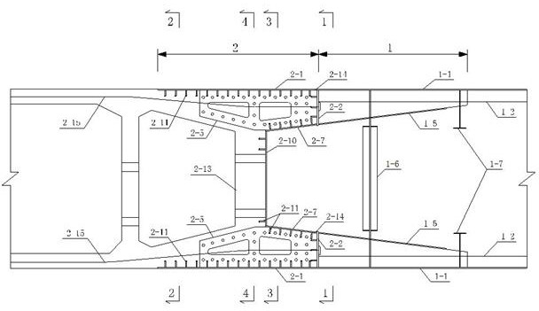
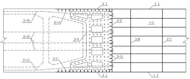
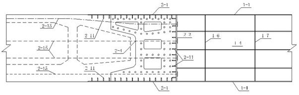
[0041] Such as Figure 1~8 As shown, a steel-concrete combination section of a semi-open cell rear panel includes a steel-concrete combination area 2 fixed to the concrete box girder, and the steel-concrete combination area 2 includes a combination section anchored to each plate of the outer profile of the concrete box girder The peripheral steel plate 2-1, the inner side of the peripheral steel plate 2-1 of the joint section is provided with a steel cell force transmission partition 2-5 along the bridge direction and located in the middle, and the inner side of the peripheral steel plate 2-1 of the joint section is also provided with The rear pressure-bearing steel plate 2-2 in the direction of the transverse bridge, the force-transmitting partition plate 2-5 of the steel cell, and the end of the rear pressure-bearing steel plate 2-2 are provided with the inner ...


PUM


Abstract

The invention discloses a rear plate type steel-concrete combined section with a semi-open grid chamber. The rear plate type steel-concrete combined section with the semi-open grid chamber comprises asteel-concrete combined area. The steel-concrete combined area comprises combined-section peripheral steel plates, steel-grid-chamber force transfer partition plates in the bridge direction are arranged on the inner sides of the combined-section peripheral steel plates, and rear pressure-bearing steel plates in the transverse direction of a bridge are further arranged on the inner sides of the combined-section peripheral steel plates. Grid-chamber inner side plates are arranged at the ends of the steel-grid-chamber force transfer partition plates and the rear pressure-bearing steel plates, asteel grid chamber is defined by the combined-section peripheral steel plates, the steel grid chamber force transfer partition plates, the rear pressure-bearing steel plates and the grid-chamber innerside plates, and concrete is poured in the steel grid chamber. The length of a closed section of the combined-section grid chamber is greatly reduced, the overall arrangement is simpler, the open space is enlarged, the grid-chamber inner side plates are obliquely arranged, and construction operation of workers is facilitated. The length of the combined section is greatly reduced compared with that of a front and rear plate type combined section, the local rigidity of a main beam is prevented from being too high, stress and deformation of the main beam are more uniform, the grid-chamber innerside plates are obliquely arranged, concrete pouring compaction is facilitated, and the engineering quality is guaranteed.

Description

technical field [0001] The invention belongs to the technical field of bridge joint sections, and in particular relates to a steel-concrete joint section with a rear panel of a semi-open cell. Background technique [0002] At present, the commonly used form of joint section of hybrid girders of highway and railway bridges is the prestressed rear slab or the prestressed front and rear slab. [0003] The prestressed back-slab joint section usually adopts the rear pressure-bearing plate and the steel cell opening on one side along the direction of the concrete beam to transmit force. The bottom plate of the cell on the upper edge of the main beam or the roof of the cell on the lower edge of the main beam are arranged horizontally, and corner gaps are likely to exist when pouring concrete , increasing the workload of construction inspection and grouting, and the horizontally arranged plates are inconvenient for workers to carry out construction welding and steel bar layout opera...

Claims


Application Information

Patent Timeline
Patent Type & Authority Applications(China)
IPC IPC(8): E01D19/12E01D2/04E01D101/24E01D101/28E01D101/30
CPCE01D2/04E01D19/125E01D2101/24E01D2101/28E01D2101/30
Inventor 苏伟杜宝军李恩良李艳刘龙张悦牟兆祥朱先意
Owner CHINA RAILWAY DESIGN GRP CO LTD
Why Eureka
Try Eureka