Wireless energy transmission frequency tracking detection circuit and implementation method

A frequency tracking and detection circuit technology, applied in frequency measurement devices and other directions, can solve problems such as the decline of product market competitiveness

Inactive Publication Date: 2020-11-24
重庆麦克斯韦尔电子科技有限公司
View PDF7 Cites 1 Cited by
  • Summary
  • Abstract
  • Description
  • Claims
  • Application Information

AI Technical Summary

Problems solved by technology

The problem is that it needs to collect two current phases for calculation
This type of technology is a control measure taken to ensure resonance, and it needs to collect a large number of data signals. The increase in the number of sensors will lead to a decline in the market competitiveness of the product

Method used


Image

  • Wireless energy transmission frequency tracking detection circuit and implementation method
  • Wireless energy transmission frequency tracking detection circuit and implementation method
  • Wireless energy transmission frequency tracking detection circuit and implementation method

Examples


Embodiment 1

[0038] Embodiment 1 circuit

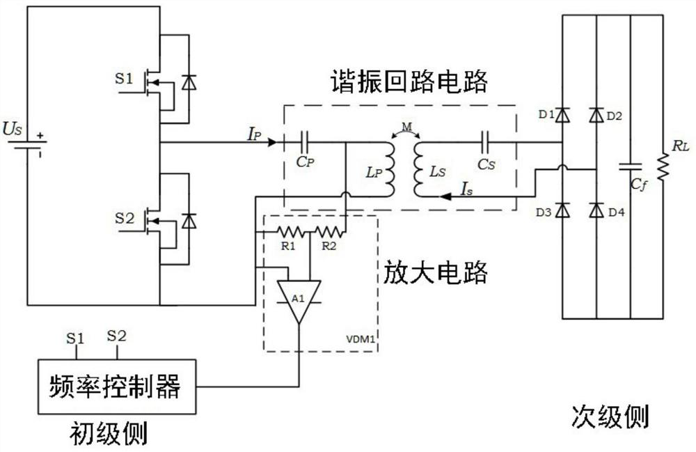
[0039] Such as figure 2 shown. A wireless energy transmission frequency tracking detection circuit, including a primary side and a secondary side, wherein the tracking circuit also includes:

[0040] A wireless energy transmission frequency tracking detection circuit, including coil voltage acquisition and amplification, wherein the tracking circuit also includes:

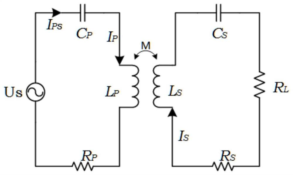
[0041] The resonant circuit circuit uses the amplitude-frequency characteristics and phase-frequency characteristics of the inductance of the resonant circuit sending coil. The square wave voltage source is injected into the resonant converter, and the RLC circuit inside the converter generates resonance, which generates high voltage on the inductance (transmitting coil). The coil and the receiving coil generate magnetic resonance coupling;

[0042] Amplifying circuit, the amplifying circuit includes inductive voltage divider resistors to amplify positive and negative signals;

[...

Embodiment 2

[0049] Example 2 method

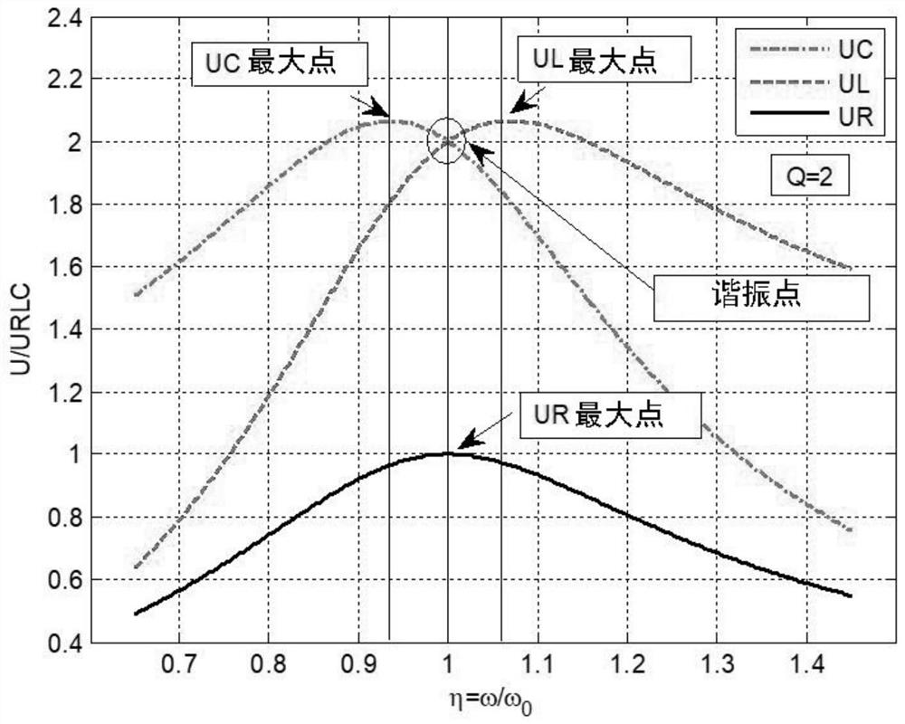
[0050] Such as Figure 3-Figure 4 As shown, a wireless energy transmission frequency tracking detection method, wherein the method includes a frequency detection method and a frequency tracking control method.

[0051] The frequency detection method is to monitor whether the transmitting end of the energy transfer system is working at the optimal frequency by collecting the voltage on the transmitting coil in the resonant circuit of the transmitting end, and then realize the control of the maximum power output through the frequency controller.

[0052] Wherein the frequency tracking control method is to control the operating frequency of the transmitting circuit after the frequency controller detects the change of the peak-to-peak value of the transmitting coil so that the voltage on the transmitting coil is the highest and the current is the largest. When the coupling coefficient changes or the load changes, the controller can Track the change of th...


PUM


Abstract

The invention discloses a wireless energy transmission frequency tracking detection circuit and an implementation method thereof. The implementation method comprises a detection principle and a detection method of resonance voltage of a transmitting coil on a primary side. The tracking circuit further comprises a sending end resonance loop circuit, an amplifying circuit and a frequency controller.The sending end resonance loop circuit utilizes the amplitude-frequency characteristic and the phase-frequency characteristic of a resonance loop sending coil inductor, a square wave voltage source is injected into a resonance converter, an RLC circuit in the converter generates resonance, and high voltage is generated on the inductor (sending coil); the amplifying circuit is used for amplifyingthe inductance voltage in the resonance circuit after high-impedance conversion sampling, completing full-wave rectification to convert the inductance voltage into a direct-current voltage signal andoutputting a voltage signal which can be identified or used by a controller; and the frequency controller is used for carrying out frequency tracking and controlling the frequency of the converter according to the acquired inductance coil voltage so as to adjust the output power of an energy transfer circuit. The working frequency of a transmitting end converter is adjusted by tracking the changeof the voltage of the transmitting coil, so that the voltage of the transmitting coil reaches the maximum value, and finally the resonant frequency in the circuit is controlled.

Description

technical field [0001] The present invention relates to the technical field of magnetic coupling resonance wireless power transmission, and more particularly relates to a wireless power transmission frequency tracking detection circuit and an implementation method. Background technique [0002] With the rapid development of electronic technology, the application of wireless energy transmission technology is becoming more and more extensive. In order to understand the shortcomings of existing technologies more clearly, please refer to the attached figure 1 Describe in detail. Among them, Lp and Ls are used to represent the sending and receiving coils of wireless energy transfer respectively, and the letter M is used to represent that the coupling coefficient is related to the distance between the coils. The letter RL represents the load equivalent resistance at the receiving end. In order to increase the transmission distance of wireless energy transfer, it is usually neces...

Claims


Application Information

Patent Timeline
Patent Type & Authority Applications(China)
IPC IPC(8): G01R23/02
CPCG01R23/02
Inventor 王世伟
Owner 重庆麦克斯韦尔电子科技有限公司
Why Eureka
Try Eureka