
Positioning and indicating device for connector wire harness processing

A positioning indication and connector technology, applied in the manufacture of wire harnesses, electrical components, circuits, etc., can solve the problems of inability to guarantee positioning accuracy, processing failure, and delayed processing efficiency, and achieve convenient and fast mobile positioning, avoid processing efficiency, Easy to change effects

Active Publication Date: 2020-11-24
深圳思锐科电子有限公司
View PDF7 Cites 1 Cited by
  • Summary
  • Abstract
  • Description
  • Claims
  • Application Information

AI Technical Summary

Problems solved by technology

[0004] The purpose of the present invention is to provide a connector wire harness processing positioning indicating device in order to solve the above problems. Through the installation structure and the moving structure, it can effectively solve the problem that the above-mentioned current positioning devices are manually adjusted, which leads to positioning There is a problem of accuracy. The processing of the wire harness has high requirements on the size, and manual adjustment cannot guarantee the accuracy of positioning, which will directly lead to the failure of processing or rework, and delay the efficiency of processing. Some positioning indicating devices are due to Due to the limited movable range, it is impossible to perform good positioning indication, and the replacement of the probes of most positioning indicating devices is cumbersome, which leads to technical problems that are not convenient for actual use.

Method used


Image

  • Positioning and indicating device for connector wire harness processing
  • Positioning and indicating device for connector wire harness processing
  • Positioning and indicating device for connector wire harness processing

Examples


Embodiment Construction

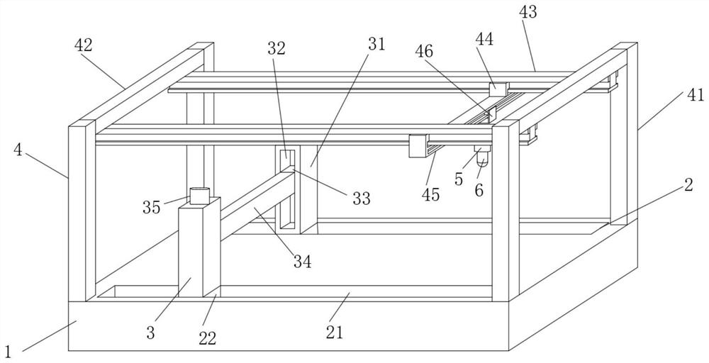
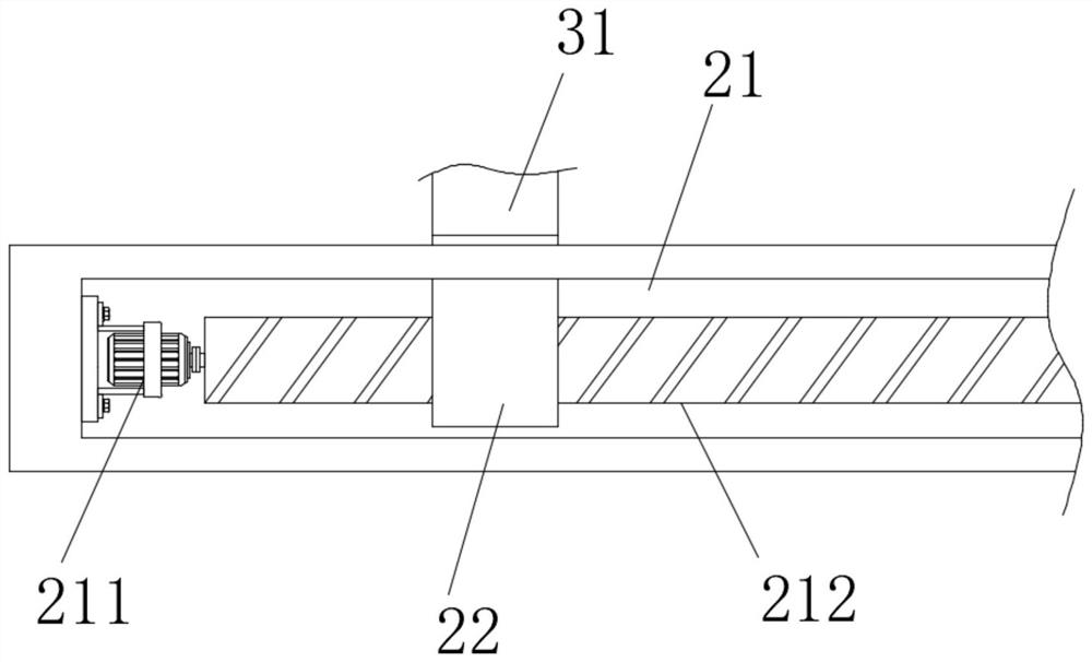
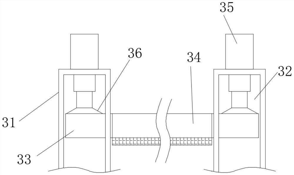
[0024] Such as Figure 1-5 As shown, this specific embodiment adopts the following technical solutions: a connector wire harness processing and positioning indicating device, including a processing platform 1, an adjustment structure 2 is provided on the top of the processing platform 1 and near the edges of both sides, and the The adjusting structure 2 is connected with a lifting structure 3, the top of the processing platform 1 is connected with a moving structure 4, the moving structure 4 is connected with a fixed plate 46, and the fixed plate 46 is connected with a mounting structure 5, the mounting structure 5 is detachably connected with a probe 6;

[0025] Described mobile structure 4 comprises supporting column 41, and described supporting column 41 is provided with four, and four described supporting columns 41 are respectively fixedly connected at the top four corners of processing platform 1, every pair of two described supporting columns 41 are opposite A crossbea...


PUM


Abstract

The invention discloses a positioning and indicating device for connector wire harness processing. The device comprises a machining platform, and adjusting structures are arranged at the positions, close to the two side edges, of the top of the machining platform. The adjusting structures are connected with a lifting structure; the top of the machining platform is connected with a moving structure. A fixed plate is connected to the moving structure; the fixed plate is connected with a mounting structure; a probe is detachably connected in the mounting structure; the clamping plates are pushedto move through the adjusting rods; the probe is clamped and fixed; the probe is convenient to replace and maintain in the future; some negative effects caused by probe replacement are avoided; the arranged cushion layer can prevent the probe from being abraded by the clamping plate, the probe can move in all directions through mutual cooperation of the first guide rail and the second guide rail,the problem that positioning is not accurate enough due to movement limitation of the probe is solved, and the specific working principle of infrared positioning is the same as the positioning principle of a laser cutting machine.

Description

Technical field: [0001] The invention belongs to the technical field of related structures of positioning indicating equipment, and in particular relates to a positioning indicating device for processing a connector wire harness. Background technique: [0002] The wire harness of the connector is to gather multiple independent wires into a whole. It is a common connector integrated circuit. When the wire harness is processed, it needs to be positioned to ensure the accuracy of the wire harness processing. , to avoid processing failure due to wire harness shaking during processing. [0003] The current positioning devices are all adjusted manually, which leads to the problem of positioning accuracy. The processing of wire harness has high requirements for size, and manual adjustment cannot guarantee the accuracy of positioning, which will directly lead to the failure of processing or rework. , the problem of delaying the efficiency of processing, and some positioning indicat...

Claims


Application Information

Patent Timeline
Patent Type & Authority Applications(China)
IPC IPC(8): H01B13/012
CPCH01B13/01209
Inventor 余和平陆梦来赵绪仁
Owner 深圳思锐科电子有限公司
Learn More