Multi-winding laminated claw-pole motor

A claw-pole motor, multi-winding technology, applied to the shape/style/structure of winding conductors, electrical components, electromechanical devices, etc. Efficiency and power factor improvement, good self-starting capability, and the effect of simplified rotor structure

Inactive Publication Date: 2020-11-24
向可为
View PDF0 Cites 1 Cited by
  • Summary
  • Abstract
  • Description
  • Claims
  • Application Information

AI Technical Summary

Problems solved by technology

[0003] Most of the existing motors are asynchronous motors, which have the characteristics of simple manufacture and low price, but also have the disadvantages of low efficiency and power factor. The existing ordinary permanent magnet synchronous motors are superior to asynchronous motors in terms of efficiency and power factor. Motors, but do not have self-starting capability, generally need to add an asynchronous starting device on the rotor to form a working condition of asynchronous starting and synchronous operation, which increases the process difficulty and cost of motor manufacturing
In addition, whether it is an asynchronous motor or an ordinary permanent magnet synchronous motor, the winding manufacturing process is time-consuming, laborious, low utilization rate of wires, low dielectric strength, and poor reliability. Motor manufacturers have deep feelings
Claw pole motors can solve the difficulty of motor winding processing, but the existing permanent magnet claw pole synchronous motors cannot pass through large alternating magnetic flux because the claw poles are integrally manufactured, so the power is not large, generally very Hard to exceed 10 watts

Method used


Image

  • Multi-winding laminated claw-pole motor
  • Multi-winding laminated claw-pole motor
  • Multi-winding laminated claw-pole motor

Examples


Embodiment Construction

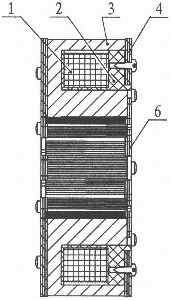
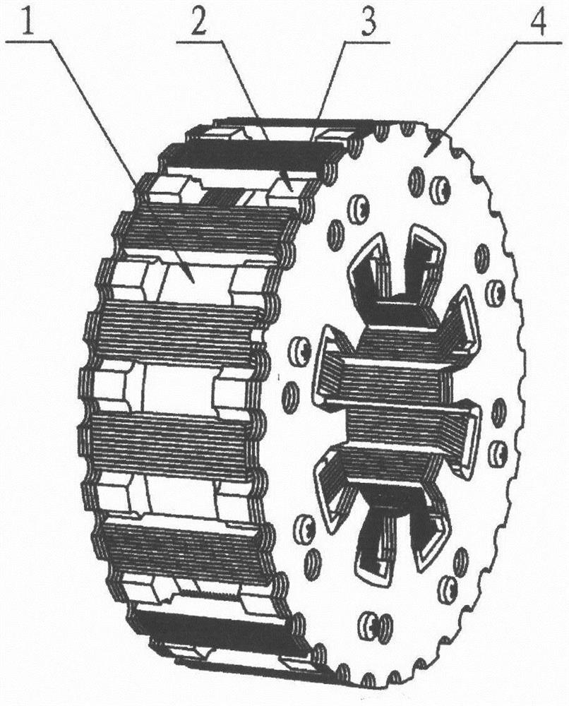
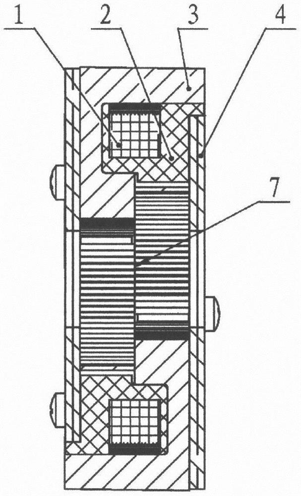
[0021] figure 1 , figure 2 It is a cross-sectional view and a three-dimensional view of the single winding combination of the inner rotor motor of the present invention. The coil (1) is wound on the skeleton (2). Since the skeleton (2) is an open structure, the winding is very convenient and efficient. The skeleton (2) uses engineering Made of plastic, on the one hand, it can improve the insulation level of the winding (1), and on the other hand, it can also provide installation support for the laminated claw poles (3). Multiple sets of laminated claw poles (3) are respectively installed into the skeleton (2) from both ends ), the two groups of laminated end plates (4) are respectively attached to the laminated claw poles (3), and are fixed on the two ends of the frame (2) to form a single winding combination (5). When working, the permanent magnet inner rotor is placed in the inner cavity of the motor stator, and the flux chain direction is: N pole of the permanent magnet i...


PUM


Abstract

The invention relates to a multi-winding laminated claw pole motor, which is mainly used for permanent magnet synchronous motor. A coil (1) is wound on a framework (2); a plurality of groups of laminated claw poles (3) are respectively arranged in the framework (2) from two ends; the two groups of laminated end plates (4) are respectively arranged at two ends of the framework (2) to form a single-winding combination (5), the laminated claw poles (3) and the laminated end plates (4) are formed by laminating a plurality of silicon steel sheets, and the motor stator can be formed by coaxially arranging two or three single-winding combinations (5) side by side and staggered at an electromagnetic angle of 90 degrees or 120 degrees in the circumferential direction. Compared with most existing motors, the motor winding processing technology is simplified, the reliability is improved, the copper consumption is reduced, compared with an existing asynchronous motor, the efficiency and the powerfactor are greatly improved, compared with an existing permanent magnet synchronous motor, the rotor structure is simplified, the cost is reduced, the self-starting capacity is good, and a high-powermotor can be manufactured.

Description

[0001] Technical field [0002] The invention relates to a multi-winding lamination claw pole motor, which is mainly used in a permanent magnet synchronous motor and belongs to the technical field of motor manufacturing. Background technique [0003] Most of the existing motors are asynchronous motors, which have the characteristics of simple manufacture and low price, but they also have the disadvantages of low efficiency and power factor. The existing ordinary permanent magnet synchronous motors are superior to asynchronous motors in terms of efficiency and power factor. Electric motors, however, do not have self-starting capabilities. Generally, an asynchronous starting device needs to be added to the rotor to form a working condition of asynchronous starting and synchronous operation, which increases the process difficulty and cost of motor manufacturing. In addition, whether it is an asynchronous motor or an ordinary permanent magnet synchronous motor, the manufacturing p...

Claims


Application Information

Patent Timeline
IPC IPC(8): H02K1/14H02K3/18H02K3/28
CPCH02K1/145H02K3/18H02K3/28H02K2213/03
Inventor 向可为
Owner 向可为
Why Eureka
Try Eureka