Shoe cabinet based on smart home

A smart home and shoe cabinet technology, applied in wardrobes, cabinets, home appliances, etc., can solve problems such as affecting foot health, breeding bacteria, and easily producing odors, avoiding self-locking bacteria, reducing odors, and high sterilization efficiency. Effect

Inactive Publication Date: 2020-11-27
宣城顺心信息技术服务有限公司
View PDF0 Cites 3 Cited by
  • Summary
  • Abstract
  • Description
  • Claims
  • Application Information

AI Technical Summary

Problems solved by technology

Often, it has to shoulder the functions of storing shoes and sundries at the same time. Most of the existing shoe cabinets are just simple cabinet structures, and shoes are easy to produce odor and breed bacteria when placed inside, which affects the health of feet.

Method used


Image

  • Shoe cabinet based on smart home
  • Shoe cabinet based on smart home
  • Shoe cabinet based on smart home

Examples


Embodiment 1

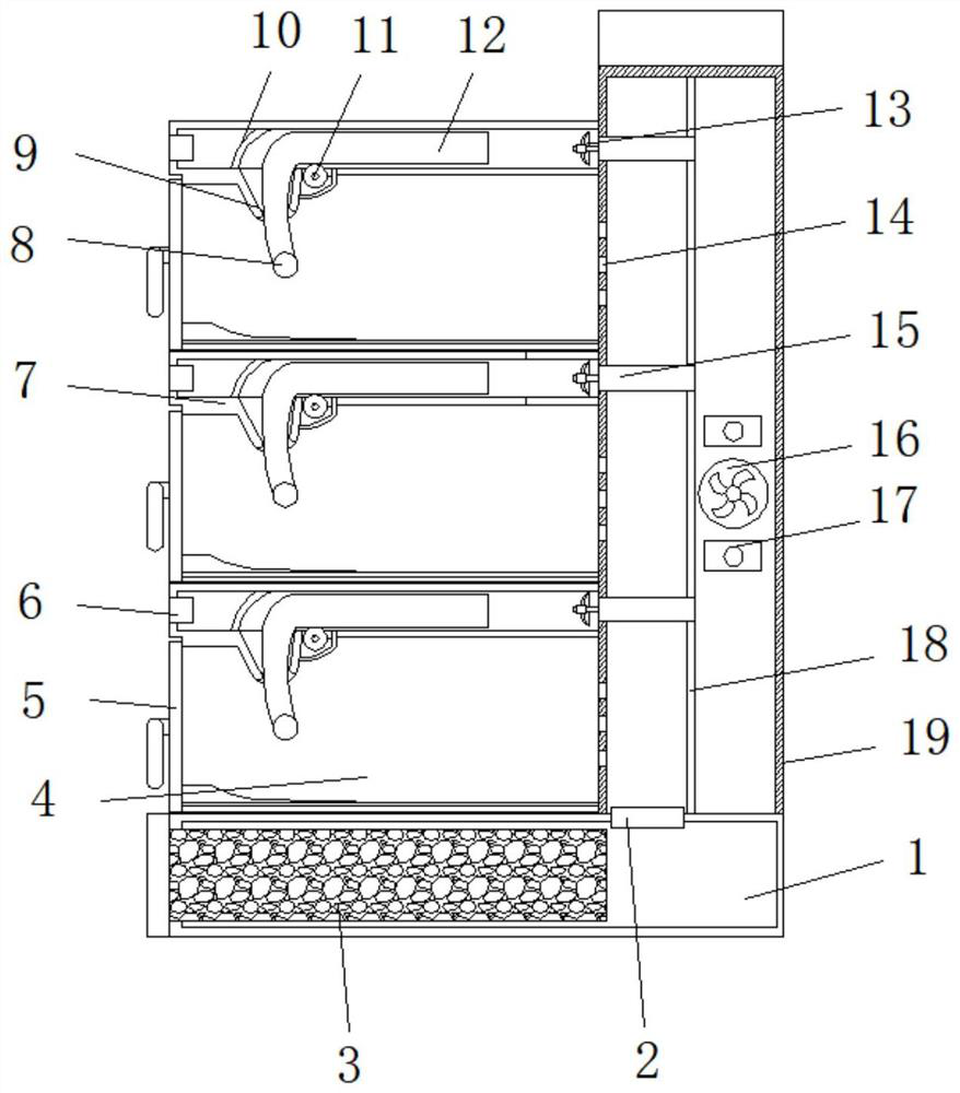
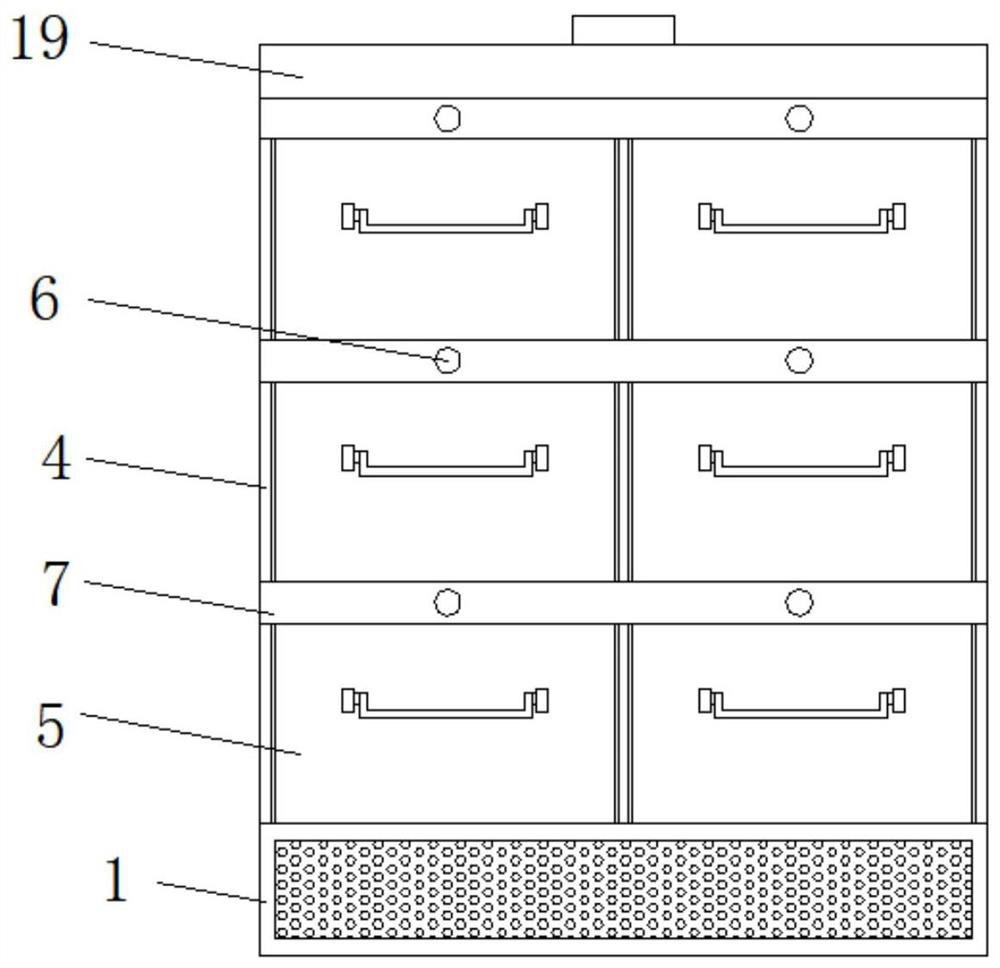
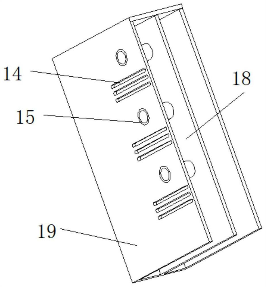
[0027] refer to Figure 1-5 , a shoe cabinet based on smart home, comprising a base box 1, a bellows 19 is fixedly installed on the top of the base box 1, and a controller is fixedly installed on the top of the bellows 19, a cabinet 4 is fixedly installed on the side of the bellows 19, and the cabinet The interior of the cabinet 4 is provided with a plurality of air ducts 7, and the interior of the cabinet 4 is provided with a plurality of cavities, and the air duct 7 is located above the cavity, and the bottom of the air duct 7 is fixedly installed with an induction switch electrically connected to the control box , the inside of the cavity is equipped with a pull-out mechanism 5 through guide rails, a partition 18 is fixedly installed inside the bellows 19, and an air duct 15 communicating with the air duct 7 is fixedly installed between the side of the partition 18 and the bellows 19, and the bellows The side of 19 is provided with a plurality of exhaust holes 14 that commu...

Embodiment 2

[0037] refer to Figure 1-5 , a shoe cabinet based on smart home. Compared with Embodiment 1 in this embodiment, the drawing mechanism 5 also includes a positioning plate 54 fixedly installed on the top of the horizontal plate 51 and arranged obliquely, and the positioning plate 54 is located below the guide tube 9 , Both sides of the horizontal plate 51 are provided with arc-shaped collection grooves 53 .

[0038] When this embodiment is in use, the positioning plate 54 is set so that the root of the shoe is placed above the inclined position when the shoe is placed, so that the bottom of the shoe produces an inclined surface, which can be directly inserted into the inside of the shoe when the air guide tube mechanism is stretched out, improving the disinfection process. stability, and the collection grooves 53 on both sides can collect the dust around the shoes, which is convenient for users to take out and clean.


PUM


Abstract

The invention discloses a shoe cabinet based on smart home, relates to the technical field of smart home and aims to solve problems that most existing shoe cabinets are of simple cabinet structures, and shoes placed in the shoe cabinets are prone to generating peculiar smells and breeding bacteria. The shoe cabinet specifically comprises a base box, wherein an air bellow is fixedly installed at the top of the base box, a controller is fixedly installed at the top of the air bellow, a cabinet body is fixedly installed on the side face of the air bellow, a plurality of air ducts are arranged inthe cabinet body, a plurality of cavities are formed in the cabinet body, and the air ducts are located above the cavities. According to the shoe cabinet, ozone flow is utilized to disinfect the interior of the shoe, in rainy seasons or humid environments, the shoe cabinet can be matched with a heater to dry the interiors of the shoes, sweat stains in the shoes are prevented from self-locking bacteria, peculiar smells in the shoes are reduced, the shoe cabinet is placed in a disinfection mode from inside to outside, sterilization efficiency is high, and sanitation consciousness of modern families is met.

Description

technical field [0001] The invention relates to the technical field of smart home, in particular to a shoe cabinet based on smart home. Background technique [0002] Smart home is based on the residence as a platform, using integrated wiring technology, network communication technology, security technology, automatic control technology, audio and video technology to integrate various devices in the home (such as audio and video equipment, lighting systems, curtain control, air conditioning system, digital cinema system, audio-visual server, video cabinet system, network appliances, etc.) to provide home appliance control, lighting control, telephone remote control, indoor and outdoor remote control, anti-theft alarm, environmental monitoring, HVAC control, infrared forwarding and Program timing control and other functions and means to build an efficient management system for residential facilities and family schedules, improve home safety, convenience, comfort, and artistry,...

Claims


Application Information

Patent Timeline
Patent Type & Authority Applications(China)
IPC IPC(8): A47B61/04A47B97/00A61L2/20B01D53/04B01D53/26A47L23/20A61L101/10
CPCA47B61/04A47B97/00A47L23/205A61L2/202B01D53/04B01D53/261
Inventor 张云凤
Owner 宣城顺心信息技术服务有限公司
Why Eureka
Try Eureka