
Limestone slurry preparation system and limestone slurry preparation method

A limestone slurry and preparation system technology, which is applied in the field of limestone slurry preparation system, can solve the problems affecting the atomization effect of the spray layer of the slurry circulating pump, the wear of the spray layer pipeline and nozzle, and the increase of the maintenance workload of the unit, so as to shorten the Downtime maintenance time, maintenance residence time, and cost-saving effects

Pending Publication Date: 2020-11-27
NORTHWEST BRANCH OF CHINA DATANG CORP SCI & TECH RES INST +1
View PDF0 Cites 1 Cited by
  • Summary
  • Abstract
  • Description
  • Claims
  • Application Information

AI Technical Summary

Problems solved by technology

[0003] Limestone-gypsum wet desulfurization system generally has the phenomenon of sediment accumulation at the bottom of the absorption tower. Most of the sediment particles are limestone particles that do not meet the grinding requirements, and a very small part are silica crystals doped in limestone ore that are not easy to grind.
A large amount of sediment accumulates at the bottom of the absorption tower. On the one hand, during the operation of the desulfurization system, the sediment particles are repeatedly sprayed and circulated with the slurry circulation pump, which causes the lining and impeller of the slurry circulation pump, the spray layer pipes and nozzles to wear, thus affecting The output of the slurry circulation pump and the atomization effect of the spray layer
On the other hand, due to the continuous deposition of large solid particles, the volume of the slurry tank of the absorption tower is reduced, which brings certain risks to the stable operation of the desulfurization system
On the other hand, during the maintenance process of the unit, it is necessary to manually clean the sediment at the bottom of the absorption tower, which greatly increases the workload of the unit maintenance and prolongs the maintenance cycle

Method used


Image

  • Limestone slurry preparation system and limestone slurry preparation method

Examples


Embodiment Construction

[0018] The present invention will be further described in detail below in conjunction with the accompanying drawings and specific embodiments.

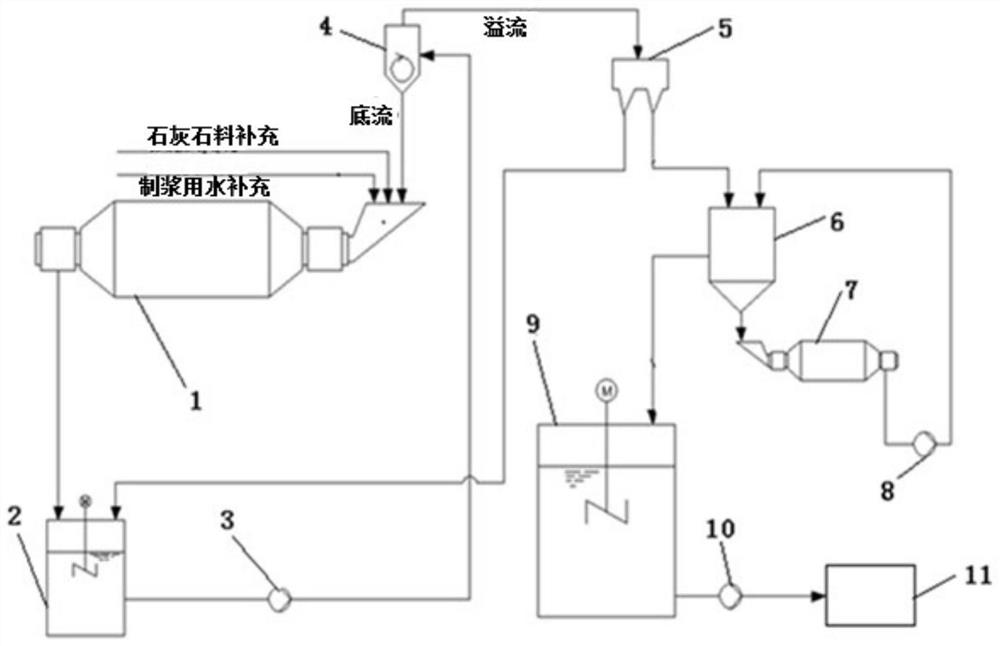
[0019] A limestone slurry preparation system of the present invention, such as figure 1 As shown, it includes primary wet ball mill 1, limestone and pulping water are replenished through the inlet of primary wet ball mill 1, and the outlet of primary wet ball mill 1 is connected to recirculation tank 2; recirculation tank 2 swirls with limestone slurry through slurry circulation pump 3 The bottom flow port of the limestone slurry cyclone 4 is connected to the inlet of the primary wet ball mill 1, the overflow port of the limestone slurry cyclone 4 is connected to the distributor 5, the distributor 5 is connected to the recirculation box 2, and the distributor 5 is also connected to The inlet of the secondary separator 6, the bottom outlet of the secondary separator 6 is connected to the inlet of the secondary wet ball mill 7, the outl...


PUM


Abstract

The invention discloses a limestone slurry preparation system. The limestone slurry preparation system comprises a primary wet ball mill, and an outlet of the primary wet ball mill is connected with arecirculation box; and the recirculation box is connected with a limestone slurry cyclone through a slurry circulating pump, an underflow opening of the limestone slurry cyclone is connected with aninlet of the primary wet ball mill, an overflow opening of the limestone slurry cyclone is connected with a distributor, the distributor is connected with an inlet of a secondary separator, an underflow opening of the secondary separator is connected with an inlet of a secondary wet ball mill, and an overflow port of the secondary separator is connected with a limestone slurry box which is connected with an absorption tower slurry pool through an absorption tower slurry supply pump. The invention also discloses a pulping method of the limestone slurry, and 90% or more of particles in the limestone slurry of the finished product are less than 40 microns. According to the limestone slurry preparation system, limestone slurry with unqualified fineness is prevented from being conveyed to the absorption tower slurry pool, equipment abrasion of a slurry circulation system is delayed, and the calcium-sulfur ratio of operation of a desulfurization system is reduced.

Description

technical field [0001] The invention belongs to the technical field of limestone-gypsum wet desulfurization equipment, and in particular relates to a limestone slurry preparation system and a slurry-making method thereof. [0002] technical background [0003] Limestone-gypsum wet desulfurization system generally has the phenomenon of sediment accumulation at the bottom of the absorption tower. Most of the sediment particles are limestone particles that do not meet the grinding requirements, and a very small part are silica crystals doped in limestone ore that are not easy to grind. . A large amount of sediment accumulates at the bottom of the absorption tower. On the one hand, during the operation of the desulfurization system, the sediment particles are repeatedly sprayed and circulated with the slurry circulation pump, which causes the lining and impeller of the slurry circulation pump, the spray layer pipes and nozzles to wear, thus affecting The output of the slurry cir...

Claims


Application Information

Patent Timeline
IPC IPC(8): B02C21/00B02C17/10B04C9/00B01D53/80B01D53/48
CPCB01D53/48B01D53/80B01D2251/404B01D2251/602B02C17/10B02C21/00B04C9/00
Inventor 贾西部黄伟岗陈鹏熊二虎张新旭郭静娟康秦豪
Owner NORTHWEST BRANCH OF CHINA DATANG CORP SCI & TECH RES INST
Learn More