Color plate color coating circulation drying and curing equipment and method

A technology of curing equipment and color steel plate, which is applied in the direction of coating, liquid coating device on the surface, pretreatment surface, etc., can solve the problems of increased nitrogen oxide generation, secondary pollution, high energy consumption, etc., and achieve waste gas utilization High efficiency, zero discharge and high treatment efficiency

Inactive Publication Date: 2020-11-27
苏州林昊板业科技有限公司
View PDF5 Cites 0 Cited by
  • Summary
  • Abstract
  • Description
  • Claims
  • Application Information

AI Technical Summary

Problems solved by technology

[0004] However, in the existing VOCs catalytic combustion equipment, when the concentration of VOCs in the exhaust gas fluctuates greatly and the concentration of organic waste gas is too low, it can only rely on adding a large amount of auxiliary fuel to supplement external heat to maintain the catalytic reaction combustion process, and adding auxiliary fuel will make the incinerator The temperature in the inner high-temperature zone is too high, resulting in an increase in the generation of nitrogen oxides, secondary pollution, and high energy consumption

Method used


Image

  • Color plate color coating circulation drying and curing equipment and method

Examples


Embodiment Construction

[0030] In order to explain the overall concept of the present invention more clearly, the following will be described in detail by way of examples in conjunction with the accompanying drawings.

[0031] In describing the present invention, it is to be understood that the terms "center", "upper", "lower", "front", "rear", "left", "right", "vertical", "horizontal", The orientation or positional relationship indicated by "top", "bottom", "inner", "outer", "axial", "radial" and "circumferential" are based on the orientation or positional relationship shown in the drawings, only It is for the convenience of describing the present invention and simplifying the description, but does not indicate or imply that the referred device or element must have a specific orientation, be constructed and operated in a specific orientation, and thus should not be construed as limiting the present invention.

[0032]In addition, the terms "first" and "second" are used for descriptive purposes only,...


PUM


Abstract

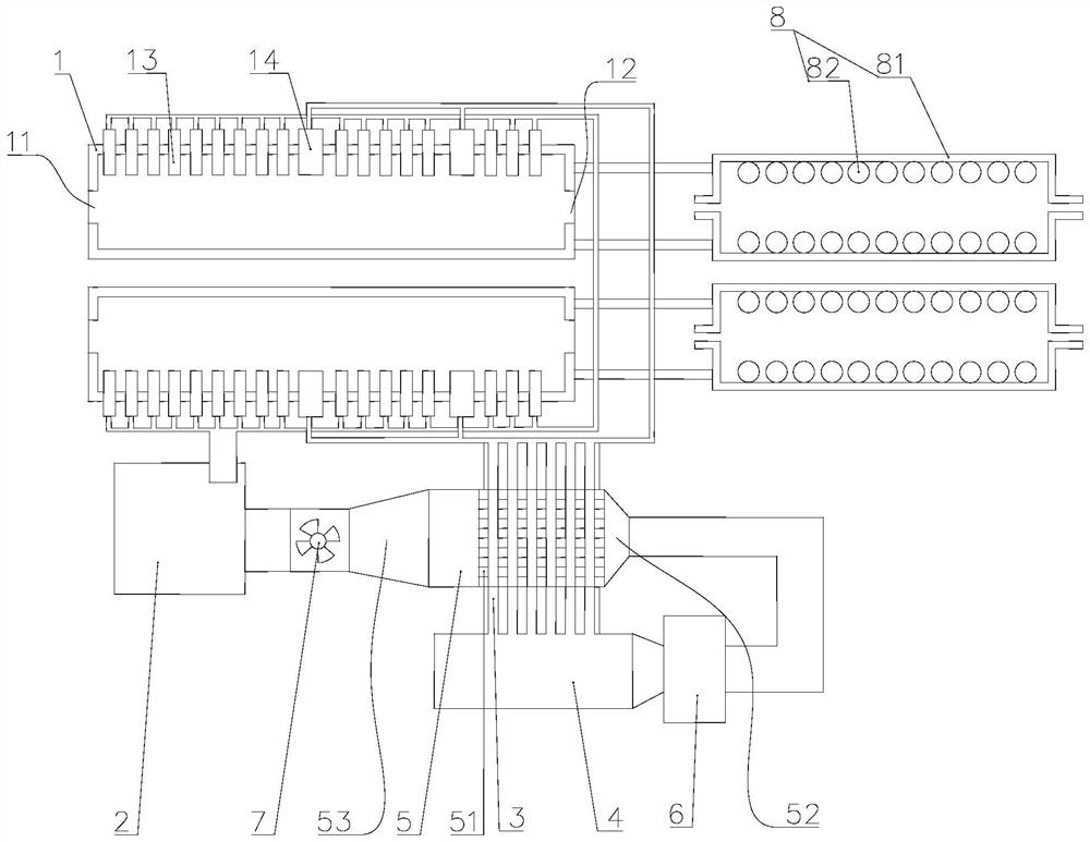
The invention discloses color plate color coating circulation drying and curing equipment and method. The color plate color coating circulation drying and curing equipment comprises drying ovens, a main combustion furnace, catalytic tubes, a waste gas combustion furnace and a catalytic box, wherein drying chambers are arranged in the drying ovens, feeding ports and discharging ports which communicate with the drying chambers are formed in the two horizontal ends of the drying ovens correspondingly, a plurality of air blowing openings and air return openings are formed in the inner side wall ofthe top and / or the bottom of the drying chamber, an outlet of the main combustion furnace communicates with the air blowing openings of the drying oven, the main combustion furnace can introduce high-temperature gas into the drying chamber, inlets of the catalytic tubes communicates with suction openings of the drying ovens, an inlet of a waste gas combustion furnace communicates with outlets ofthe catalytic tubes, catalysts are uniformly arranged in the catalytic box, a gas inlet and a gas outlet are arranged in the catalytic box, the gas inlet of the catalytic box communicates with an outlet of the waste gas combustion furnace, the gas outlet of the catalytic box communicates with an inlet of the main combustion furnace, and the two drying ovens are stacked in the vertical direction, the multiple catalytic tubes are arranged in the catalytic box in a penetrating mode, and inlets and outlets of the catalytic tubes penetrate out of the catalytic box.

Description

technical field [0001] The invention belongs to the technical field of color steel plate processing, and in particular relates to a color steel plate color coating cycle drying and curing equipment and method. Background technique [0002] The color steel plate drying and curing equipment is to dry the painted color steel plate, so as to facilitate the rapid accumulation of the painted color steel plate, and it is not easy to cause serious paint drop. There are many types and quantities of drying and curing equipment for color steel plates on the market, but there are some problems, such as very low drying efficiency of color steel plates, and the coloring after drying is not durable. [0003] In addition, a large amount of VOCs (Volatile Organic Compounds, volatile organic compounds) will be produced during the baking and curing process after color coating of the steel plate. VOCs are volatile and active in nature, and can participate in atmospheric photochemical reactions ...

Claims


Application Information

Patent Timeline
Patent Type & Authority Applications(China)
IPC IPC(8): B05D3/04B05D3/06
CPCB05D3/04B05D3/067
Inventor 蒋伟
Owner 苏州林昊板业科技有限公司
Why Eureka
Try Eureka