Laser welding machine for lithium battery edge covering

A laser welding machine and lithium battery technology, applied in laser welding equipment, welding equipment, metal processing equipment, etc., can solve the problems of laser intensity impact on precision laser welding, inconvenient use, and quality reduction of laser welding products, etc., to achieve convenient adjustment of welding The effect of point position

Inactive Publication Date: 2020-11-27
广州华赋知识产权咨询有限公司
View PDF5 Cites 0 Cited by
  • Summary
  • Abstract
  • Description
  • Claims
  • Application Information

AI Technical Summary

Problems solved by technology

[0003] At present, laser welding for lithium batteries mainly uses a small laser welding machine. When the existing laser welding machine is in use, part of the heat will be generated during the laser welding process, and this heat will act on the lithium battery. There will be some sundries in the pool, the existing laser welding machine does not deal with this part of the sundries, and if the sundries are not cleaned up in time, it will inevitably affect the accuracy of laser welding and the quality of laser welding. The intensity of the laser will affect the quality of laser welding products, which will affect the reputation of users in severe cases.
[0004] Laser welding machines in the prior art are generally fixed in a certain place for use, and the welding points of laser welding often need to be adjusted during the laser welding process, and this laser welding machine lacks an adjustment device for welding points. For more complex laser welding, it seems powerless, and it is not very convenient to adjust the horizontal and vertical positions of the laser welding machine, and there are many inconveniences in use.

Method used


Image

  • Laser welding machine for lithium battery edge covering
  • Laser welding machine for lithium battery edge covering
  • Laser welding machine for lithium battery edge covering

Examples


Embodiment Construction

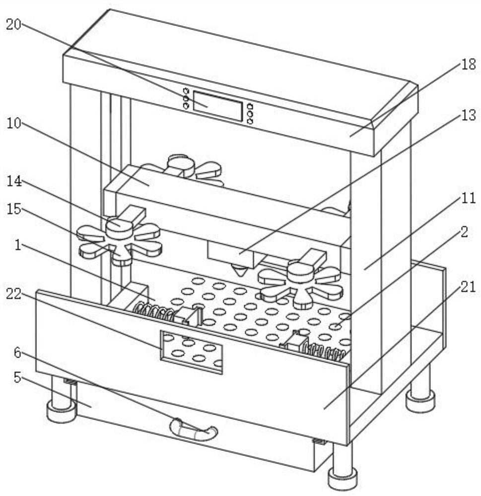
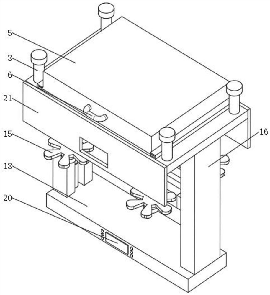
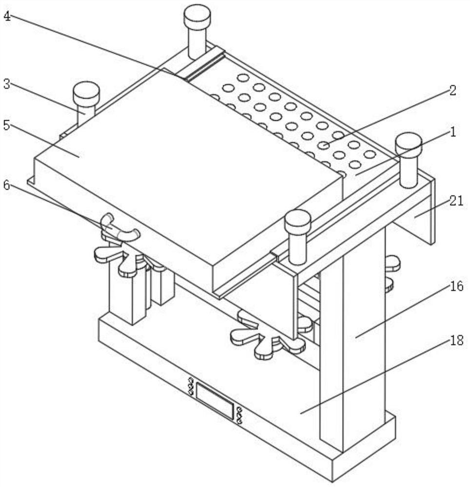
[0056] The following will clearly and completely describe the technical solutions in the embodiments of the present invention with reference to the accompanying drawings in the embodiments of the present invention. Obviously, the described embodiments are only some, not all, embodiments of the present invention. Based on the embodiments of the present invention, all other embodiments obtained by persons of ordinary skill in the art without making creative efforts belong to the protection scope of the present invention.

[0057] see Figure 1-5 , a laser welding machine for lithium battery hemming, including a base 1, the top of the base 1 is provided with through holes 2 in a matrix, and slide rails 4 are fixedly installed on the left and right sides of the bottom of the base 1, and the two slide rails Between 4, the chip box 5 that is positioned at the bottom of the through hole 2 is installed movably, and the front of the chip box 5 is fixedly equipped with a handle 6, and t...


PUM


Abstract

The invention relates to the technical field of laser welding, and discloses a laser welding machine for lithium battery edge covering. The laser welding machine comprises a base, through holes are formed in the top end of the base in a matrix shape, sliding rails are fixedly arranged on the left side and the right side of the bottom end of the base, and a scrap collecting box located below the through holes is movably arranged between the two sliding rails. According to the laser welding machine for lithium battery edge covering, the through holes are formed in the top end of the base in thematrix shape, the sliding rails are fixedly arranged on the left side and the right side of the bottom end of the base, the scrap collecting box is movably arranged between the sliding rails, a handleis fixedly arranged on the front face of the scrap collecting box, when waste scraps need to be cleaned, the waste scraps can be transmitted into the scrap collecting box located below the base through the through holes, at the moment, the scrap collecting box can collect the waste scraps, and when the scrap collecting box is full of the waste scraps, the handle can be pulled to drive the scrap collecting box to move relative to the sliding rails so as to dismount the scrap collecting box for dumping, and the advantage of collecting the waste scraps is achieved.

Description

technical field [0001] The invention relates to the technical field of laser welding, in particular to a laser welding machine used for edge wrapping of lithium batteries. Background technique [0002] "Lithium battery" is a type of battery that uses lithium metal or lithium alloy as the positive / negative electrode material and uses a non-aqueous electrolyte solution. In 1912, the lithium metal battery was first proposed and studied by Gilbert N. Lewis. In the 1970s, M.S.Whittingham proposed and began to study lithium-ion batteries. Due to the very active chemical properties of lithium metal, the processing, storage and use of lithium metal have very high environmental requirements. With the development of science and technology, lithium batteries have become the mainstream, and a kind of laser welding is often used in the process of wrapping lithium batteries. Laser welding is an efficient and precise welding method that uses a high-energy-density laser beam as a heat sou...

Claims


Application Information

Patent Timeline
Patent Type & Authority Applications(China)
IPC IPC(8): B23K26/21B23K26/08B23K26/70
CPCB23K26/0869B23K26/21B23K26/702B23K26/703
Inventor 魏娟
Owner 广州华赋知识产权咨询有限公司
Why Eureka
Try Eureka