Axle box guide pillar positioning type three-axis welding self-guiding radial wagon bogie

A railway freight car, positioning technology, applied in the direction of bogie, railway car body parts, axle box installation, etc., can solve the problems of eccentric brake shoe wear, serious wear, excessive self-weight, etc., and achieve simple mechanical structure and high transmission efficiency. Effect

Pending Publication Date: 2020-11-27
CHENGDU TECHCAL UNIV
View PDF0 Cites 1 Cited by
  • Summary
  • Abstract
  • Description
  • Claims
  • Application Information

AI Technical Summary

Problems solved by technology

For a long time, due to the complex structure, the three-axis bogie has faced many technical problems that need to be solved, such as insufficient stability, easy interference between parts, excessive self-weight, serious wear, and eccentric wear of brake shoes, etc.

Method used


Image

  • Axle box guide pillar positioning type three-axis welding self-guiding radial wagon bogie
  • Axle box guide pillar positioning type three-axis welding self-guiding radial wagon bogie
  • Axle box guide pillar positioning type three-axis welding self-guiding radial wagon bogie

Examples


Embodiment 1

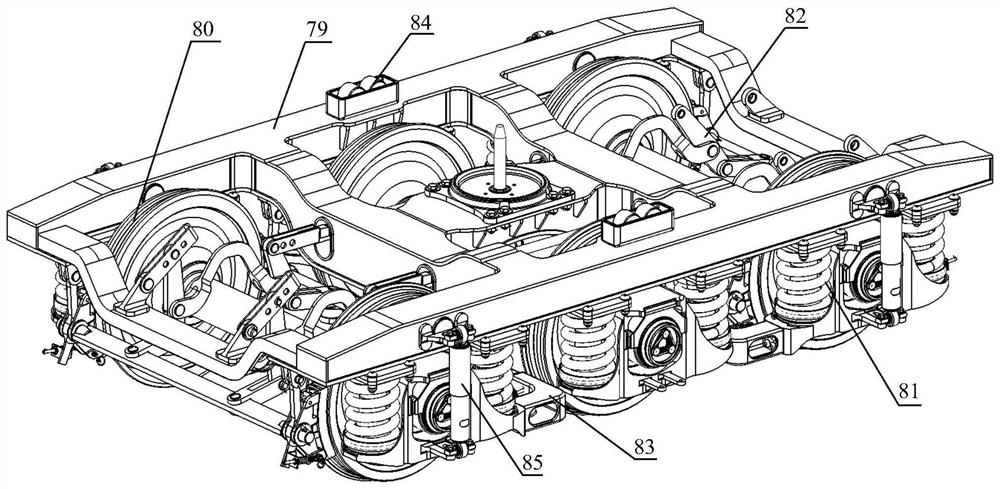
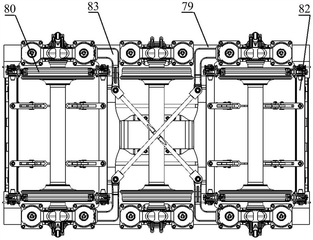
[0089] Such as figure 1 and figure 2 The illustrated three-axis welded self-guiding radial railway freight car bogie with axle box guide column positioning type includes a frame 79, three sets of wheel set assemblies 80 matched with the frame 79, and the two ends of the main shaft of the wheel set assembly 80 are They are all matched with an axle box suspension device 81, and also include a basic brake device 82 for braking the wheel set assembly 80. The main shafts of the wheel set assemblies 80 on both sides are end shafts, and the two end shafts correspond to The four axle box suspension devices 81 are connected by a cross connection device 83, and a vertical hydraulic damping device 85 is installed between the four axle box suspension devices 81 corresponding to the two end shafts and the frame 79; Clearance side bearings 84 are all set on both sides along the track direction on the 79.

[0090] The wheel rim of the wheel set assembly 80 located in the middle is thinner...

Embodiment 2

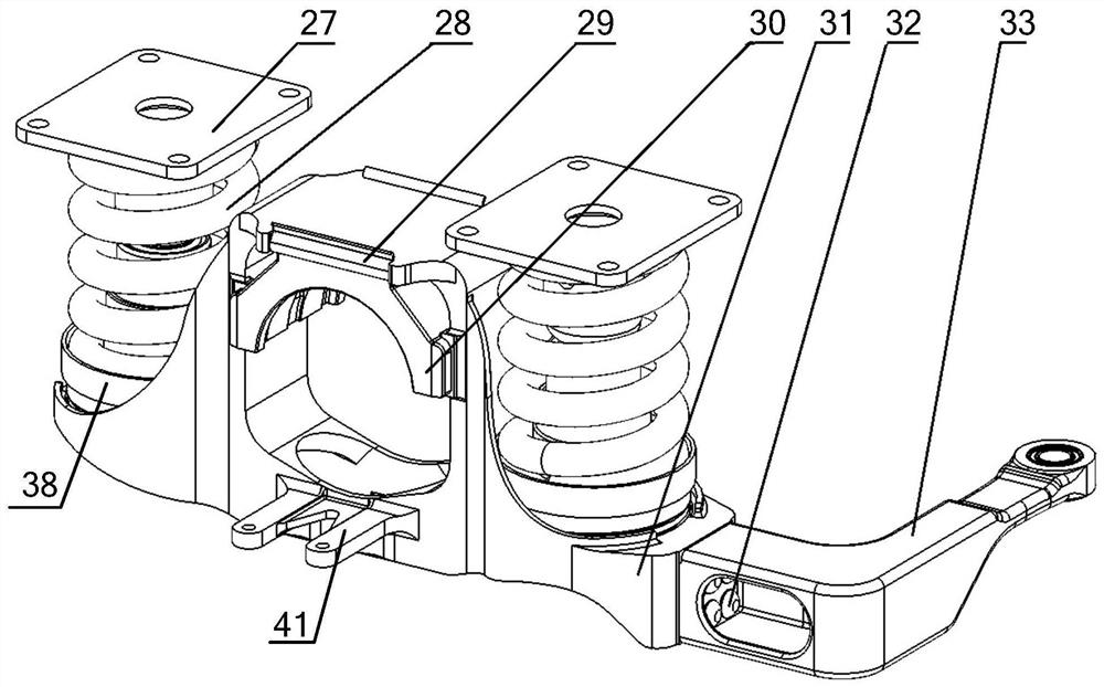
[0096] On the basis of Embodiment 1, the axle box suspension device 81 is as Figure 3 ~ Figure 4 As shown, it includes an axle box 31 for cooperating with rolling bearings, and an axle box spring 28 matched with the axle box 31. The bearing saddle 30 is detachably connected to the axle box 31, and the axle box 31 and the bearing saddle 30 are jointly formed. In the installation part of the rolling bearing, a number of wear plates 29 are installed on the top of the bearing saddle 30; it also includes a guide post assembly arranged on both sides of the axle box 31, and the axle box spring 28 is located in the guide post assembly assembly. The guide post assembly assembly includes a guide post assembly 27 for installation on the welding frame, a guide post assembly 34 fixed below the guide post assembly 27, an elastic positioning sleeve 35 fixed below the guide post assembly 34; It includes a positioning seat composition 40 located on the axle box 31, an annular buffer pad 39 is...

Embodiment 3

[0104] On the basis of Embodiment 1, the foundation braking device such as Figure 5 ~ Figure 10 As shown, the two-side brake shoe suspension brake is adopted for the two-end wheel sets, the plate beam type brake beam double-rod structure, and the middle wheel set has no brake. specific:

[0105] Including plate beam type brake beam 1, fixed lever fulcrum 2, fixed lever 3, bow tie rod 4, middle lever 5, straight tie rod 6, floating lever 7, brake shoe head automatic adjustment device 8, high-friction composite brake shoe 9. Brake shoe support 10, brake shoe support crane 11.

[0106] The main beam of the brake beam 1 is a straight plate brake beam with a plate structure, and the center position of the straight plate brake beam is symmetrically riveted with one pillar 13 on both sides, and the end shafts 12 are welded along the longitudinal surface at both ends; the brake shoe support 10 is a cast structure, Its back is a double-walled web groove structure, and a circular thr...


PUM


Abstract

The invention discloses an axle box guide pillar positioning type three-axis welding self-guiding radial wagon bogie which includes a framework, three groups of wheel set assemblies matched with the framework, and a basic braking device, wherein axle box suspension devices are connected to the two ends of main shafts of the wheel set assemblies in a matched mode; the basic braking device is used for braking the wheel set assemblies, main shafts of the wheel set assemblies located on the two sides are end shafts, the four axle box suspension devices corresponding to the two end shafts are connected through cross connection devices, and vertical hydraulic damping devices are installed between the four axle box suspension devices corresponding to the two end shafts and the framework. Gap sidebearings are arranged on the two sides, in the rail direction, of the framework. The invention provides the axle box guide pillar positioning type three-axis welding self-guiding radial railway wagonbogie to solve the problems in the prior art and achieve the purposes of simplifying the structure of the three-axis bogie and improving the working performance of the three-axis bogie.

Description

technical field [0001] The invention relates to the field of railway freight cars, in particular to a three-axis welded self-guiding radial railway freight car bogie with axle box guide column positioning. Background technique [0002] Heavy-duty transportation is the development direction of railway freight. Efforts to increase the load capacity of freight trains is a major aspect of improving railway transport capacity and economic benefits, and increasing the carrying capacity of bogies is one of the most effective ways to increase the load capacity of vehicles and thus the load capacity of the entire freight train. Usually, there are two ways to increase the bearing capacity of the bogie: increasing the axle load of the bogie and using a multi-axle bogie with three or more axles. Due to the influence of lines and bridges, the allowable axle load of bogies is limited to a certain extent. Therefore, when transporting some heavy-duty special cargo, using bogies with three ...

Claims


Application Information

Patent Timeline
IPC IPC(8): B61F5/26B61F3/02
CPCB61F3/02B61F5/26
Inventor 李志强李雨杭韩丽荣王健豪张慧云李航高荣张光才罗汉江祝笈吴畅
Owner CHENGDU TECHCAL UNIV
Why Eureka
Try Eureka