
Shell-breaking full-mixing type anaerobic reactor

An anaerobic reactor, fully mixed technology, applied in anaerobic digestion treatment, chemical instruments and methods, special treatment targets, etc., can solve the problem that raw materials and fermentation bacteria cannot be fully mixed, float on the surface of raw material liquid, and biogas is not easy to escape. and other problems, to achieve the effect of improving biogas yield and raw material utilization rate

Active Publication Date: 2020-11-27
INNER MONGOLIA UNIVERSITY
View PDF6 Cites 3 Cited by
  • Summary
  • Abstract
  • Description
  • Claims
  • Application Information

AI Technical Summary

Problems solved by technology

However, the applicant found in actual research that the existing shell-breaking full-mix anaerobic reactor still has the following problems in use: when the shell-breaking mechanism is working, the shell-breaking part rotates around the central axis of the stirring shaft and destroys the buoyancy. The scum shell, this method of breaking the shell can destroy the scum shell on the surface of the raw material liquid into massive "scum blocks", but it cannot further destroy or clean the scum blocks, so that the scum blocks will still float On the surface of the raw material liquid, more and more floating scum blocks will make it difficult for the generated biogas to escape, resulting in a decrease in the biogas yield of the reactor; moreover, the floating scum blocks will also prevent the raw materials and fermentation bacteria from fully mixing , leading to a decrease in the raw material utilization of the reactor

Method used


Image

  • Shell-breaking full-mixing type anaerobic reactor
  • Shell-breaking full-mixing type anaerobic reactor
  • Shell-breaking full-mixing type anaerobic reactor

Examples


Embodiment

[0042] This embodiment discloses a broken-shell full-mix anaerobic reactor.

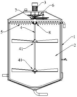
[0043] Such as figure 1 Shown: a broken-shell fully mixed anaerobic reactor, including a cylindrical shell 1 with a reaction chamber 2, a stirring shaft 4 vertically arranged in the reaction chamber 2 along the central axis of the shell 1, and a driving shaft 4 for driving The driving device 3 for rotating the stirring shaft 4; two groups of stirring paddles 41 are arranged at intervals along the central axis on the stirring shaft 4 .

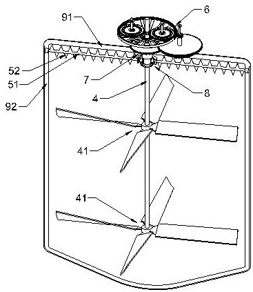
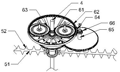
[0044] combine figure 2As shown: the shell-breaking full-mix anaerobic reactor of this embodiment also includes a shell-breaking mechanism 5 arranged in the reaction chamber 2, and a horizontal transmission mechanism 7 and a longitudinal transmission mechanism 8 respectively connected to the stirring shaft 4; The shell mechanism 5 includes a shell-breaking beam 51 transversely arranged in the reaction chamber 2, and a shell-breaking assembly arranged on the shell-b...


PUM


Abstract

The invention particularly relates to a shell-breaking full-mixing type anaerobic reactor which comprises a cylindrical shell with a reaction cavity, a stirring shaft vertically arranged in the reaction cavity along the central axis of the shell, and a driving device used for driving the stirring shaft to rotate. The shell-breaking full-mixing type anaerobic reactor also comprises a shell breakingmechanism arranged in the reaction cavity, and a transverse transmission mechanism and a longitudinal transmission mechanism in transmission connection with the stirring shaft respectively. The shellbreaking mechanism comprises a shell breaking cross beam transversely arranged in the reaction cavity and a shell breaking assembly arranged on the shell breaking cross beam; the transverse transmission mechanism is used for driving the shell breaking cross beam to rotate along the central axis of the stirring shaft when the stirring shaft rotates; and the longitudinal transmission mechanism is used for driving the shell breaking cross beam to rotate along the central axis of the longitudinal transmission mechanism when the stirring shaft rotates. The shell-breaking full-mixing type anaerobicreactor can effectively destroy and clean scum shells and scum blocks on the surface of the raw material liquid, so that the biogas yield and the raw material utilization rate of the reactor can be improved in an auxiliary manner.

Description

technical field [0001] The invention relates to the technical field of biogas preparation, in particular to a broken shell fully mixed anaerobic reactor. Background technique [0002] Fully mixed anaerobic reactor is an anaerobic treatment device that makes fermentation raw materials and microorganisms in a completely mixed state. It is used in slaughterhouse wastewater, livestock and poultry manure treatment and biogas production in cattle, pigs, chickens and other farms , Power generation projects, urban domestic sludge and other high-concentration organic wastewater treatment projects. [0003] The existing fully mixed anaerobic reactor includes a cylindrical shell forming a reaction chamber inside, a stirring shaft vertically arranged in the reaction chamber along the central axis of the shell, and a driving device for driving the stirring shaft to rotate; the reaction chamber It is used to fill the raw material liquid; the stirring shaft is provided with stirring blade...

Claims


Application Information

Patent Timeline
Patent Type & Authority Applications(China)
IPC IPC(8): C02F3/28C02F11/04
CPCC02F3/28C02F11/04C02F2303/14Y02E50/30
Inventor 许继飞柳亚宁朱天骄于瑞宏郭伟赵吉
Owner INNER MONGOLIA UNIVERSITY
Learn More