Hydraulic power generation system

A technology of hydraulic power generation and power generation system, which is applied in the direction of hydropower generation, engine components, machines/engines, etc. It can solve the problems of difficulty in system testing, increased cost of power generation devices, and inconvenient installation and maintenance. It is suitable for large-scale promotion and application , Easy installation and maintenance, safe and reliable operation

Pending Publication Date: 2020-11-27
NINGBO AUX ELECTRIC +1
View PDF0 Cites 1 Cited by
  • Summary
  • Abstract
  • Description
  • Claims
  • Application Information

AI Technical Summary

Problems solved by technology

[0005] The power generation form adopted by the existing water flow power generation device, the whole system is installed underwater, which is very inconvenient for installation and maintenance. At the same time, the installation of the system underwater also brings difficulties to the system test
All of these lead to an increase in the cost of power generation devices

Method used


Image

  • Hydraulic power generation system
  • Hydraulic power generation system

Examples


Embodiment 1

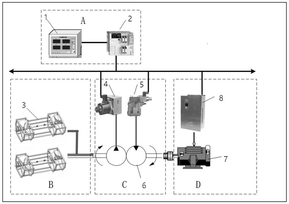
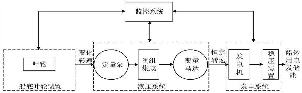
[0037] Example 1, such as Figure 1~2 As shown, the present invention discloses a hydraulic power generation system, including a hull, an impeller system B, a hydraulic energy conversion system C, and a power generation system D. The impeller system B is arranged below the hull, and the impeller device B acts on the movement of the hull. The hydraulic energy conversion system C and the power generation system D are arranged on the hull, and the hydraulic energy conversion system C will be able to perform the conversion of kinetic energy-mechanical energy-hydraulic energy under the action of the rotation of the impeller device B. The generator of the power generation system D is in transmission connection with the hydraulic energy conversion system C, the generator rotates at a constant speed under the action of the control system, and the power generation system D provides electricity and / or energy storage for the hull.

[0038] Preferably, the impeller device B can be rotated by...


PUM


Abstract

The invention provides a hydraulic power generation system. A ship body, an impeller system B, a hydraulic transduction system C and a power generation system D are included, and the impeller system Bis arranged below the ship body; the impeller device B can rotate under the moving action of the ship body, the hydraulic transduction system C and the power generation system D are arranged on the ship body, the hydraulic transduction system C can conduct kinetic energy-mechanical energy-hydraulic energy conversion under the rotating action of the impeller device B, and a power generator rotatesat a constant speed under the action of a control system. According to the design, an impeller is mounted at the bottom of a ship; the impeller and a quantitative hydraulic pump are directly connected and rotate synchronously, all control components and execution components are placed on a cabin through the system, on one hand, water flow is generated during ship body running, the impeller rotates through water flow impact force, then the power generator rotates at a constant speed under the action of the control system, and therefore constant-frequency stable power generation is achieved. Onthe other hand, installation and maintenance are convenient, system debugging tests are simple, and cost is reduced.

Description

Technical field [0001] The invention relates to the technical field of power generation equipment, in particular to a hydraulic power generation system. Background technique [0002] With the excessive development and depletion of fossil fuel energy, the resulting global energy crisis and environmental pollution have become the focus of close attention by countries all over the world. Therefore, the scientific development and comprehensive utilization of renewable energy represented by water flow energy, solar energy and wind energy have important theoretical and practical significance for mankind to alleviate energy crisis and environmental pollution. [0003] Water flow power generation is an important part of clean energy and renewable energy. The development and construction of hydroelectric power generation has a multi-level energy construction function, which is the comprehensive utilization of water resources, and can better promote the comprehensive management of rivers, s...

Claims


Application Information

Patent Timeline
Patent Type & Authority Applications(China)
IPC IPC(8): F03B13/00F03B11/00
CPCF03B11/00F03B13/00Y02E10/20
Inventor 刘亚洲易红艳梁维博
Owner NINGBO AUX ELECTRIC
Why Eureka
Try Eureka