
Heat dissipation device for moving electrocaloric refrigeration device based on electromagnet

A technology of refrigeration devices and heat sinks, which is applied to machines, refrigerators, refrigeration and liquefaction using electrical/magnetic effects, etc., which can solve the problem of poor refrigeration capacity of electric card refrigeration devices, limited promotion and application, and insufficient heat of electric card refrigeration devices. Efficient release and other issues

Active Publication Date: 2020-11-27
NANJING UNIV OF SCI & TECH
View PDF17 Cites 7 Cited by
  • Summary
  • Abstract
  • Description
  • Claims
  • Application Information

AI Technical Summary

Problems solved by technology

[0004] Although the electric card refrigeration device can obtain better cooling capacity, the current electric card refrigeration technology cannot transfer heat efficiently, and the heat absorbed by the electric card refrigeration device cannot be efficiently released to the external environment, resulting in the The continuous refrigeration capacity is very poor, which restricts its practical application
In order to solve this problem, there is currently a way to use a thermoelectric refrigeration device composed of semiconductor couples to transfer heat from the electric card refrigeration device. This is an ideal heat cycle device. This refrigeration cycle does not require refrigerants. Moving parts, no noise, no vibration, no wear, but it has high cost, low efficiency, complex manufacturing, and must use direct current, these shortcomings limit its promotion and application

Method used


Image

  • Heat dissipation device for moving electrocaloric refrigeration device based on electromagnet
  • Heat dissipation device for moving electrocaloric refrigeration device based on electromagnet
  • Heat dissipation device for moving electrocaloric refrigeration device based on electromagnet

Examples


Embodiment Construction

[0023] The specific embodiments of the present invention will be further described below in conjunction with the accompanying drawings.

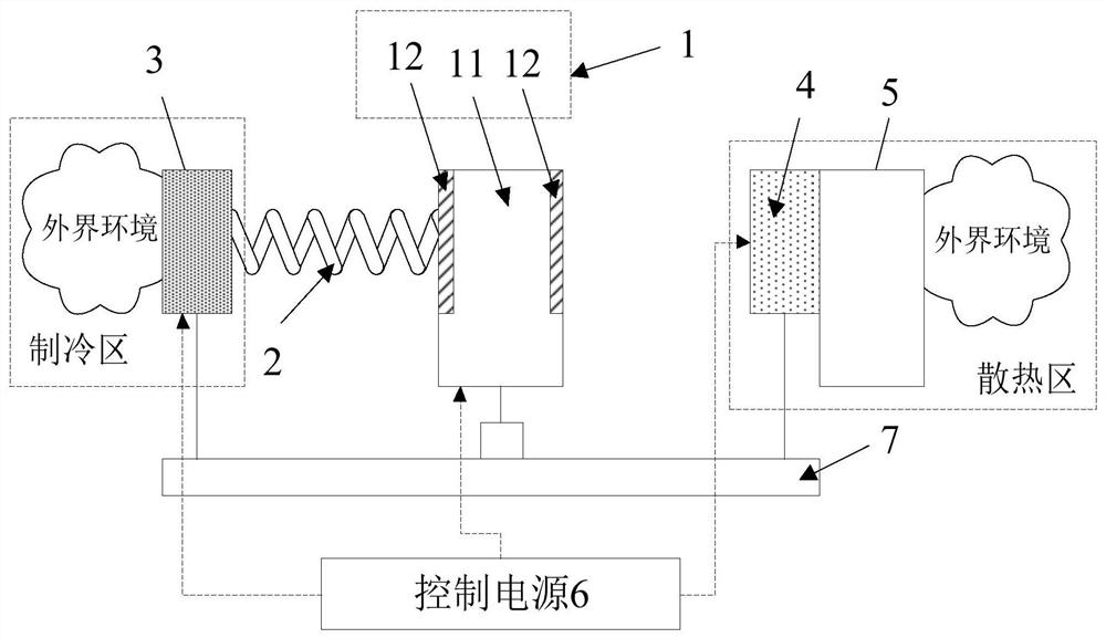
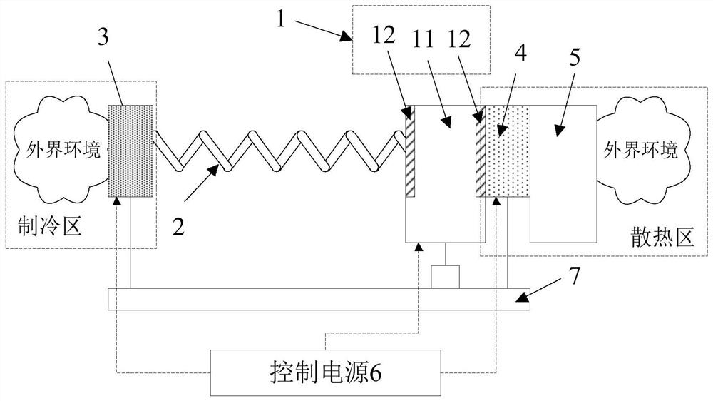
[0024] This application discloses a cooling device based on electromagnet mobile electric card refrigeration device, please refer to figure 1 , the heat dissipation device includes an electric card refrigeration device 1, a buffer spring 2, an electromagnet 3 in a cooling zone, an electromagnet 4 in a heat dissipation zone, a heat sink 5 and a control power supply 6.

[0025] The electromagnet 3 in the cooling area and the electromagnet 4 in the cooling area are arranged oppositely. The electromagnet 3 in the cooling area and the external environment on the side thereof constitute a cooling area. , the cooling area electromagnet 4, the heat sink 5 and the external environment on the side thereof constitute the cooling area. The two electromagnets in this application can be realized by common commercial electromagnets, which are composed of ...


PUM


Abstract

The invention discloses a heat dissipation device for moving an electrocaloric refrigeration device based on electromagnets, and relates to the technical field of refrigeration. The heat dissipation device comprises a refrigeration area electromagnet and a heat dissipation area electromagnet which are oppositely arranged, the refrigeration area electromagnet and the external environment of the side where the refrigeration area electromagnet is located form a refrigeration area; the heat dissipation area electromagnet, a cooling fin and the external environment on the side where the cooling finis located form a heat dissipation area, and the electrocaloric refrigeration device is connected with the refrigeration area electromagnet through a buffer spring, located between the heat dissipation area and the refrigeration area and at least comprises an electrocaloric refrigeration element and a magnetic element. The heat dissipation device utilizes the magnetic attraction effect between the electromagnets and the magnetic element to be combined with the elastic effect of the buffer spring to control the movement of the electrocaloric refrigeration device so as to realize the heat circulation release function, is simple in structure, can directly utilize alternating current, and on the basis of realizing the same effect of circulating work, the electrocaloric refrigeration device isnoiseless in operation, high in efficiency, low in loss, simple in mechanical operation and free of pollution to the environment.

Description

technical field [0001] The invention relates to the technical field of refrigeration, in particular to a heat dissipation device based on an electromagnet to move an electric card refrigeration device. Background technique [0002] Refrigeration technology can be found everywhere and is widely used in daily life such as the use of air conditioning and cold air and preservation of fresh food, in industrial production processes such as low temperature treatment of steel, in the pharmaceutical industry such as vaccines and organ preservation In the processing of electronic devices such as heat dissipation of electronic components. However, with the continuous improvement of the level of science and technology and the rapid development of the national economy, the harm caused by traditional refrigeration technology to the environment is also increasing, leading to the greenhouse effect, which causes global warming, and also has a great impact on the ozone layer. destructive eff...

Claims


Application Information

Patent Timeline
IPC IPC(8): F25B21/00
CPCF25B21/00Y02B30/00
Inventor 汪尧进杨斌潘韩宋树文鑫荣
Owner NANJING UNIV OF SCI & TECH
Learn More