
Ceramic brick sintering device for building

A technology of sintering device and ceramics, applied in furnace control device, charge composition/state, charging processing type, etc., can solve problems such as billet cracks, inconvenient control of temperature in the kiln, etc., to avoid cracks and reduce heat loss.

Inactive Publication Date: 2020-11-27
诸暨市仲达智能科技有限公司
View PDF1 Cites 1 Cited by
  • Summary
  • Abstract
  • Description
  • Claims
  • Application Information

AI Technical Summary

Problems solved by technology

[0006] Aiming at the deficiencies of the prior art, the present invention provides a ceramic brick sintering device for construction, which solves the problem that the existing ceramic brick sintering device in the above-mentioned background technology is inconvenient to control the temperature in the kiln, and the blank is easy to change due to temperature. The problem of cracking too fast

Method used


Image

  • Ceramic brick sintering device for building
  • Ceramic brick sintering device for building
  • Ceramic brick sintering device for building

Examples


Embodiment Construction

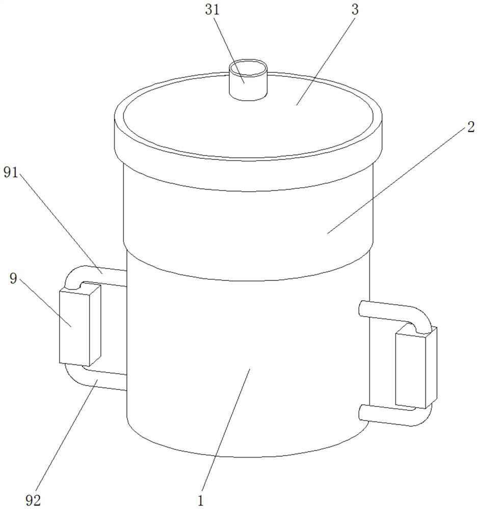
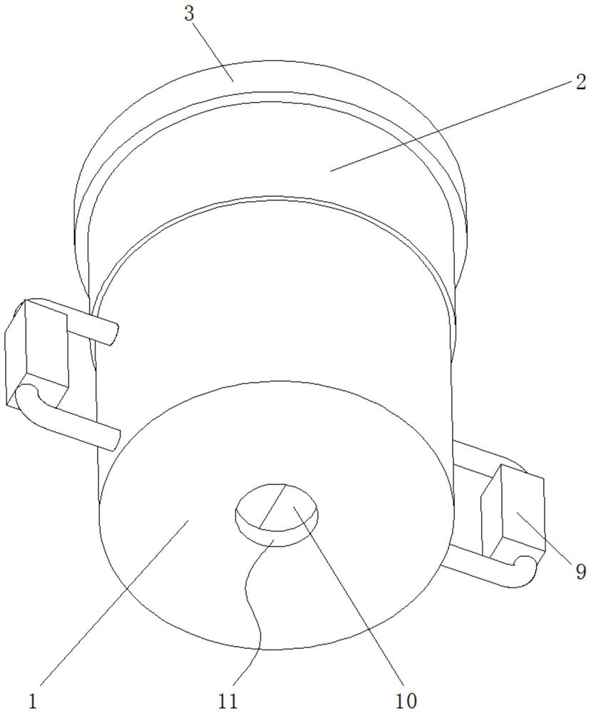
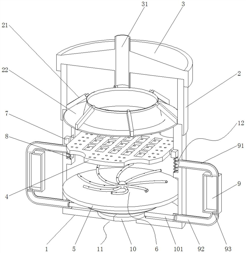
[0026] Embodiments of the present invention provide a ceramic brick sintering device for construction, such as Figure 1-7 As shown, it includes a kiln body 1, a tank body 2 and a top cover 3. An air inlet 11 is opened in the center of the bottom of the kiln body 1 . A combustion furnace is fixedly installed below the kiln, and the high-temperature airflow generated by combustion in the combustion furnace enters the kiln through the air inlet 11 . Because this is the prior art, so the concrete structure of the combustion furnace, connection mode etc. are identical with conventional technical means, do not describe in detail and no longer draw in the accompanying drawings.

[0027] The tank body 2 is fixedly installed on the top of the kiln body 1 , and the top cover 3 is fixedly installed on the top of the tank body 2 . The kiln body 1 is provided with a placing plate 4, and the placing plate 4 is used for placing ceramic bricks. The top of the top cover 3 is provided with ...


PUM


Abstract

The invention provides a ceramic brick sintering device for a building, and relates to the field of building equipment. The ceramic brick sintering device for the building comprises a kiln body, a tank body and a top cover, wherein an air inlet is formed in the center of the bottom of the kiln body, the tank body is arranged at the top of the kiln body, and the top cover is arranged at the top ofthe tank body. According to the ceramic brick sintering device for the building, a placing plate, a sliding block and a spring are matched with one another, after a blank is sintered into a ceramic brick, water is evaporated, the weight is reduced, so that an air pipe is exposed out of the upper body of the placing plate, and the detection effect is achieved; a storage bin, the air pipe, a water pipe and a heat conducting piece are matched, a piston rod is pushed by means of the heated transpiration of the liquid, so that two sealing plates are close to each other to seal the air inlet; the effect of automatically closing the air inlet after sintering is achieved; and then the sealing plates, an electric push rod and a heat insulation plate are matched, the kiln body is sealed, and the loss of hot air is reduced; and the situation that the ceramic brick cracks due to the fact that the temperature change is large because of the rapid loss of heat after sintering is avoided.

Description

technical field [0001] The invention relates to the technical field of construction equipment, in particular to a ceramic brick sintering device for construction. Background technique [0002] Ceramic bricks are used in building masonry [0003] In production, it is necessary to put the billet into the firing furnace and sinter it at high temperature. When the sintering is completed, the flame in the kiln stops burning so that the temperature in the kiln drops rapidly, and the blank will cause cracks in the produced ceramic block due to the change of the kiln temperature. Once cracks and flaws appear in the ceramic tiles, the bearing capacity of the ceramic tiles will be weakened. [0004] The quality of the products is not up to standard. These defective or damaged products cannot enter the sales channel and can only be discarded. This has caused a great waste of resources and a huge burden on the natural environment. Contents of the invention [0005] (1) Solved techn...

Claims


Application Information

Patent Timeline
IPC IPC(8): F27B17/00F27B19/00
CPCF27B17/005F27B19/00F27D2019/0068F27D2019/0093F27M2001/1517F27M2003/04
Inventor 龙玖燕朱家坤
Owner 诸暨市仲达智能科技有限公司
Learn More