
A method for producing an integral flat brush

A production method and integral technology, applied in the field of integral flat brush production, can solve problems such as low efficiency, high labor intensity, and poor contact, and achieve the effects of avoiding easy deformation, improving fault tolerance, and improving production efficiency

Active Publication Date: 2021-10-08
徐洪杰
View PDF10 Cites 0 Cited by
  • Summary
  • Abstract
  • Description
  • Claims
  • Application Information

AI Technical Summary

Problems solved by technology

[0003] At this stage, in the production and processing of conductive slip rings, due to too many parts in the product structure design, a lot of manual assembly is required, especially in the assembly stage of brush wires, because most of the brush wires are copper or precious metal alloys with certain elasticity The material is relatively soft. When assembling the wires on the slip ring, it is very challenging for the eyes of the workers, and the efficiency is low. The brush wires after assembly are often deformed, resulting in poor contact, and the angle needs to be adjusted manually again. , so it is difficult to control the contact angle between the brush wire and the conductive copper ring, which affects the electrical performance of the product, and the labor intensity is high
[0004] Its authorization announcement number CN209709353U-name is a kind of integrated conductive slip ring, discloses a kind of pre-assembled brush holder, namely at first the brush wire of vertical installation is assembled on the plate frame, correspondingly installed on the plate frame with two Row of brush wires, which fix the brush wires to the corresponding holes on the brush board by means of reassembly, and carry out the overall assembly on the plate frame at any time, which is still the assembly of the brush wires, and cannot get rid of the troublesome assembly of the brush wires the fundamental problem

Method used


Image

  • A method for producing an integral flat brush
  • A method for producing an integral flat brush
  • A method for producing an integral flat brush

Examples


Embodiment Construction

[0028] The following will clearly and completely describe the technical solutions in the embodiments of the present invention with reference to the accompanying drawings in the embodiments of the present invention. Obviously, the described embodiments are only some, not all, embodiments of the present invention. Based on the embodiments of the present invention, all other embodiments obtained by persons of ordinary skill in the art without creative efforts fall within the protection scope of the present invention.

[0029] In describing the present invention, it is to be understood that the terms "opening", "upper", "lower", "thickness", "top", "middle", "length", "inner", "surrounding" etc. Indicating orientation or positional relationship is only for the convenience of describing the present invention and simplifying the description, and does not indicate or imply that the components or elements referred to must have a specific orientation, be constructed and operated in a sp...


PUM


Abstract

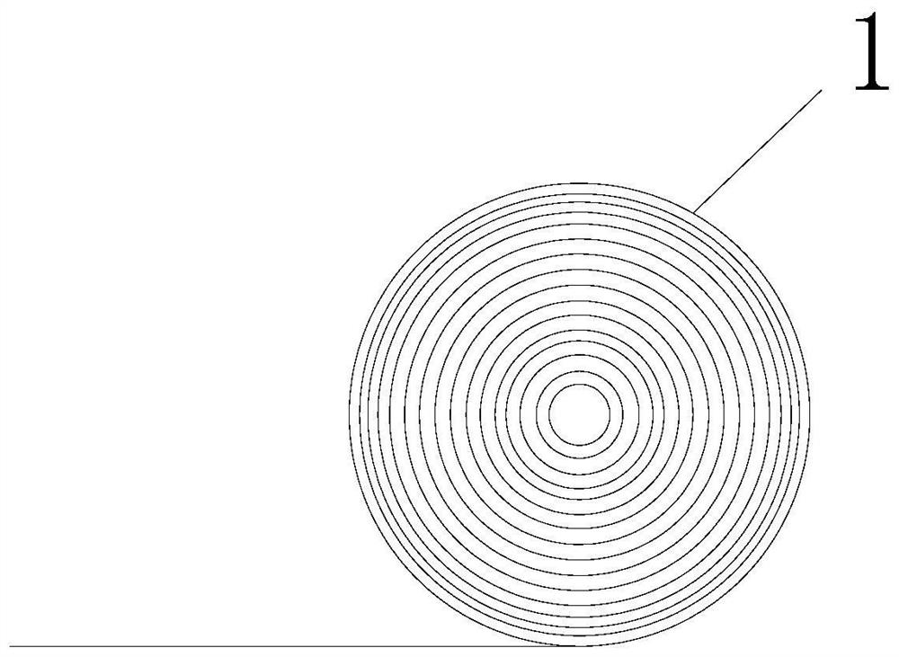
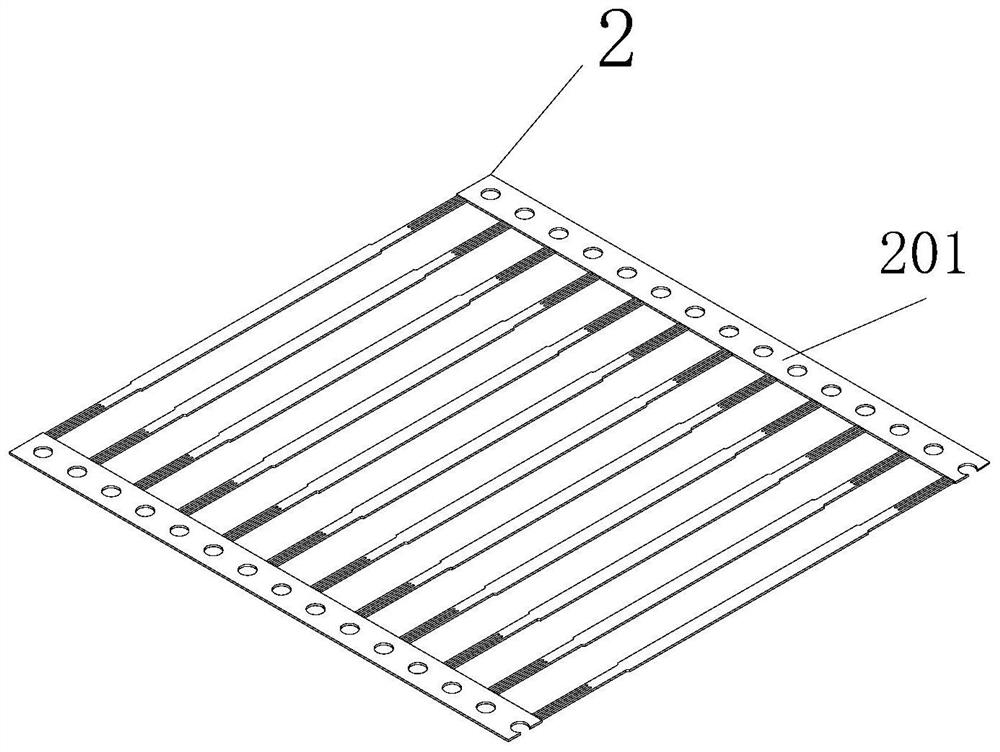
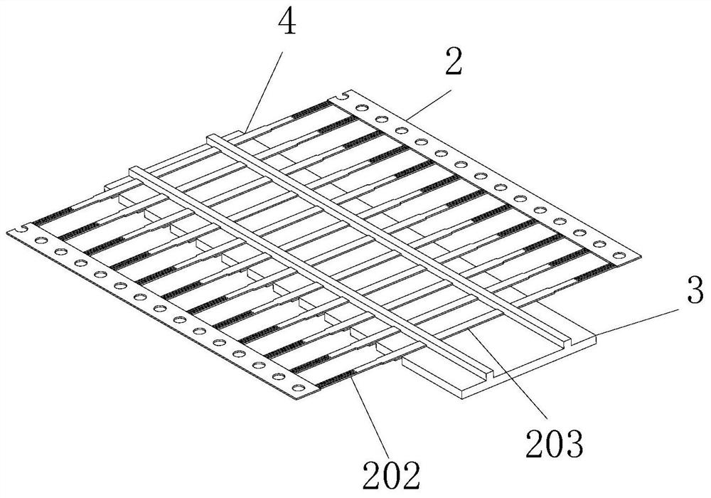
The invention discloses a method for producing an integral flat electric brush, which belongs to the technical field of production of conductive slip rings. The invention includes stamping, punching the plate to be processed to make it into rows and connected associated brush wires; injection molding, injecting plastic substrates on the associated brush wires to form an integrated primary conjoined wire board; cutting, cutting off the associated brush wires The ties used to connect the brush body and the one-piece wire board that is cut out to a prefabricated length from the initial one-piece wire board. After the injection molding is completed, the brush wire body protruding from the side of the plastic substrate along with the brush wire is the brush board section, and the rest Part of it is an embedded section, which also includes bending. The brush plate section is folded in the same direction, and the bending is carried out in any process after the stamping is completed. The present invention reduces the process of brush filament assembly by producing a conjoined wire plate in which the brush wire body and the injection molded wire board are integrated.

Description

technical field [0001] The invention belongs to the technical field of production of conductive slip rings, and in particular relates to a production method of an integral flat plate brush. Background technique [0002] At present, conductive slip rings belong to the application category of electrical contact sliding connections. A precision power transmission device that realizes the image, data signal and power transmission of two relative rotating mechanisms. [0003] At this stage, in the production and processing of conductive slip rings, due to too many parts in the product structure design, a lot of manual assembly is required, especially in the assembly stage of brush wires, because most of the brush wires are copper or precious metal alloys with certain elasticity The material is relatively soft. When assembling the wires on the slip ring, it is very challenging for the eyes of the workers, and the efficiency is low. The brush wires after assembly are often deforme...

Claims


Application Information

Patent Timeline
Patent Type & Authority Patents(China)
IPC IPC(8): H01R43/12
CPCH01R43/12
Inventor 徐洪杰
Owner 徐洪杰
Features
  • Generate Ideas
  • Intellectual Property
  • Life Sciences
  • Materials
  • Tech Scout
  • Unparalleled Data Quality
  • Higher Quality Content
  • 60% Fewer Hallucinations
Learn More