Dynamic comparator circuit with low power consumption

A dynamic comparator, low-power technology, applied in multiple input and output pulse circuits, electrical components, pulse processing, etc., can solve problems such as reducing leakage current power consumption, high power consumption, and reducing circuit dynamic power consumption, etc. Achieve the effect of reducing dynamic power consumption, low power consumption, and reducing leakage current power consumption

Inactive Publication Date: 2020-11-27
UNIV OF ELECTRONIC SCI & TECH OF CHINA +1
View PDF6 Cites 0 Cited by
  • Summary
  • Abstract
  • Description
  • Claims
  • Application Information

AI Technical Summary

Problems solved by technology

[0004] Aiming at the problem of high power consumption in the above-mentioned traditional dynamic comparator, the present invention proposes a low-power dynamic comparator circuit, which connects the third NMOS transistor M4 and the third PMOS transistor M5 to the differential output end of the dynamic comparator between the cross-coupling transistors, that is, the first PMOS transistor M6 and the second PMOS transistor M7, and the power supply voltage VDD are provided with a stacked transistor 205, the fourth PMOS tra

Method used


Image

  • Dynamic comparator circuit with low power consumption
  • Dynamic comparator circuit with low power consumption

Examples


Embodiment Construction

[0014] The technical scheme of the present invention will be described in detail below in conjunction with the accompanying drawings and embodiments.

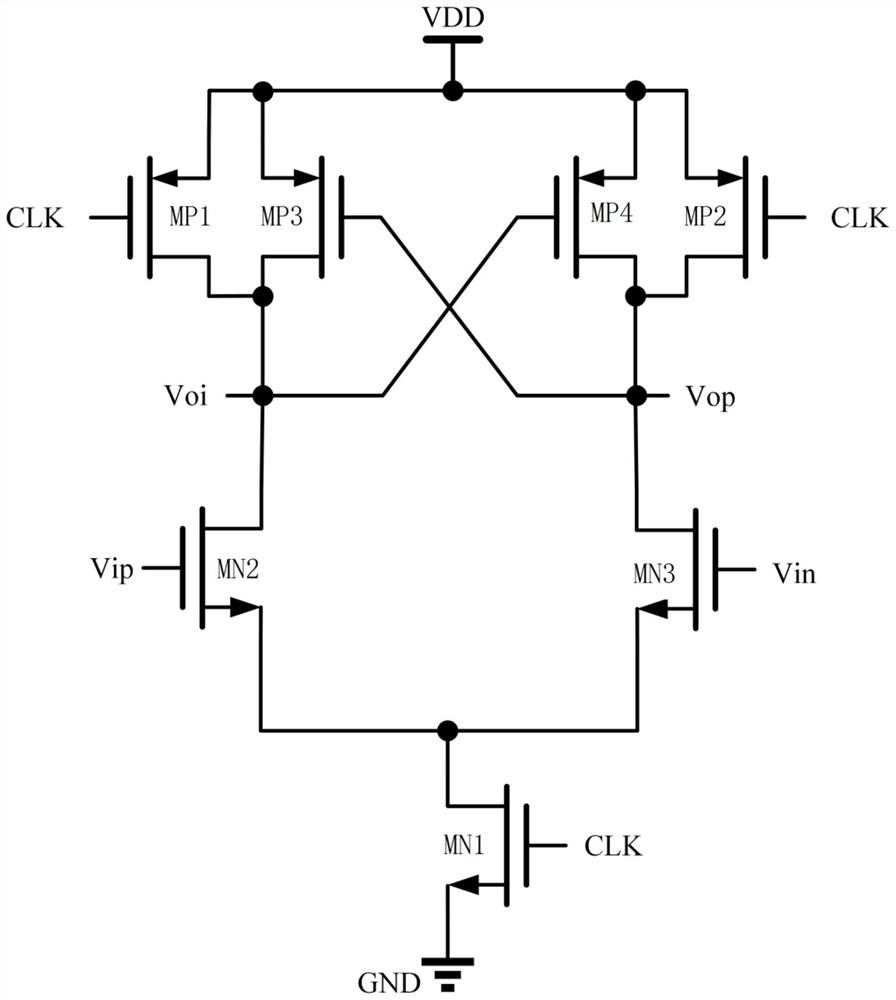
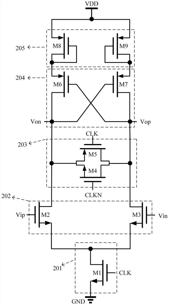
[0015] The present invention proposes a low power consumption dynamic comparator circuit, such as figure 2 As shown, it includes a bias module for providing DC bias. In this embodiment, the bias module adopts a bias transistor 201, which is the fourth NMOS transistor M1, and the gate of the fourth NMOS transistor M1 is connected to the clock The source of the signal CLK is grounded, and the drain is used as the output terminal of the bias module. The first NMOS transistor M2 and the second NMOS transistor M3 are input transistors 202, the first PMOS transistor M6 and the second PMOS transistor M7 are cross-coupled transistors 204, and the gate of the first NMOS transistor M2 is used as the positive input of the dynamic comparator circuit The terminal is connected to the positive input signal Vip, and its drain is connected to...


PUM


Abstract

The invention discloses a dynamic comparator circuit with low power consumption. A grid electrode of a first NMOS tube is used as a positive input end of the dynamic comparator circuit, the drain electrode of the first NMOS tube is connected with the drain electrode of a first PMOS transistor, the grid electrode of a second PMOS transistor, the source electrode of a third PMOS transistor and the source electrode of a third NMOS transistor and serves as the negative output end of the dynamic comparator circuit, and the source electrode of the first NMOS tube is connected with the source electrode of the second NMOS transistor and direct current bias provided by the bias module; the grid electrode of the second NMOS transistor is used as the negative input end of the dynamic comparator circuit, and the drain electrode of the second NMOS transistor is connected with the drain electrode of the second PMOS transistor, the grid electrode of the first PMOS transistor, the drain electrode of the third PMOS transistor and the drain electrode of the third NMOS transistor and is used as the positive output end of the dynamic comparator circuit; gates of the third PMOS transistor and the thirdNMOS transistor are respectively connected with a clock signal and an inverting signal thereof; the gate and drain of the fourth PMOS transistor are in short circuit and connected with the source ofthe first PMOS transistor, the gate and drain of the fifth PMOS transistor are in short circuit and connected with the source of the second PMOS transistor, and the source of the fourth PMOS transistor and the source of the fifth PMOS transistor are connected with a power supply voltage. According to the invention, the dynamic power consumption is reduced by reducing the output reset level of thecomparator, and the stacked tubes also reduce the leakage current power consumption.

Description

technical field [0001] The invention belongs to the technical field of analog circuit signal processing, and in particular relates to a dynamic comparator circuit with low power consumption. Background technique [0002] Comparators are one of the important analog circuit modules in modern integrated circuit systems, and are widely used in AD / DA conversion systems, automotive electronics, biomedical and other fields. With the continuous development of the integrated circuit industry, the power consumption requirements for a single module are particularly prominent. As one of the common and important modules, the comparator can greatly benefit from the reduction of its power consumption. [0003] figure 1 It is a traditional dynamic comparator circuit, and its basic working principle is to use the difference between the input voltages of the input pair tubes (ie, NMOS transistors MN2 and MN3) in the comparator comparison stage, thereby generating two currents with a differe...

Claims


Application Information

Patent Timeline
IPC IPC(8): H03K5/24
CPCH03K5/249
Inventor 李靖尧博文田明于奇宁宁
Owner UNIV OF ELECTRONIC SCI & TECH OF CHINA
Why Eureka
Try Eureka