
Mutual redundancy power supply system and method for adjacent electric fields of electric precipitator

A technology of electrostatic precipitator and power supply system, applied in the direction of power supply technology, electrostatic separation, etc., which can solve the problems of electric field power supply, excessive dust emission, and affecting the dust collection efficiency of the electrostatic precipitator

Inactive Publication Date: 2020-12-01
XIAN XIKUANG ENVIRONMENTAL PROTECTION
View PDF7 Cites 1 Cited by
  • Summary
  • Abstract
  • Description
  • Claims
  • Application Information

AI Technical Summary

Problems solved by technology

[0003] Each electric field of the electrostatic precipitator is powered independently by a high-voltage power supply. When any power supply fails, it cannot supply power to the corresponding electric field, resulting in the entire electric field not working. However, the dust collection area of ​​one electric field of the electrostatic precipitator generally occupies the entire 20-50% of the total dust collection area of ​​a dust collector, which seriously affects the dust collection efficiency of the electrostatic precipitator, resulting in excessive dust emissions

Method used


Image

  • Mutual redundancy power supply system and method for adjacent electric fields of electric precipitator
  • Mutual redundancy power supply system and method for adjacent electric fields of electric precipitator
  • Mutual redundancy power supply system and method for adjacent electric fields of electric precipitator

Examples


Embodiment Construction

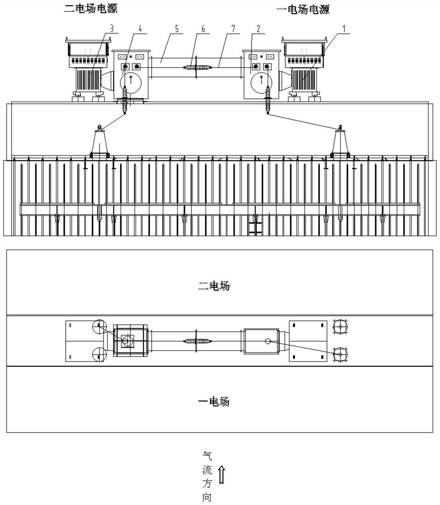
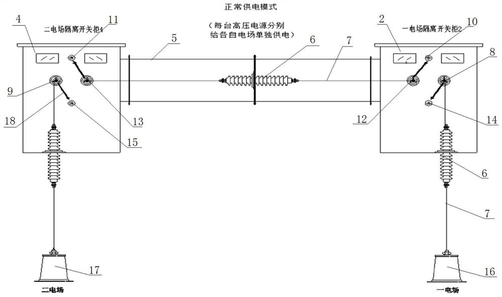
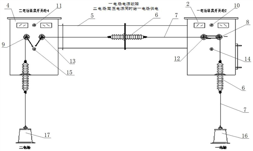
[0024] Such as Figure 1 to Figure 4 As shown, the electric dust collector adjacent electric field mutual redundancy power supply system of the present invention includes a first high-voltage silicon rectifier transformer 1, a first isolation switch cabinet 2, a second high-voltage silicon rectifier transformer 3, a second isolation switch cabinet 4, and a connecting sleeve Tube 5, wall-piercing insulating sleeve 6, connecting wire 7, first high-voltage input terminal 14, second high-voltage input terminal 15, first electric field connecting terminal 8, second electric field connecting terminal 9, first grounding terminal 10, second The ground terminal 11 , the first electric field standby connecting terminal 12 and the second electric field standby connecting terminal 13 . The first high-voltage silicon rectifier transformer 1 is connected to the first high-voltage input terminal 14, and the second high-voltage silicon rectifier transformer is connected to the second high-vol...


PUM


Abstract

The invention relates to a mutual redundancy power supply system for adjacent electric fields of an electric precipitator. The system comprises a first high-voltage silicon rectifier transformer, a second high-voltage silicon rectifier transformer, a connecting wire, a first high-voltage input end, a second high-voltage input end, an electric field connection end, a second electric field connection end, an electric field standby connection end and a second electric field standby connection end. The first high-voltage silicon rectifier transformer is connected with an electric field connectionend, the second high-voltage silicon rectifier transformer is connected with a second electric field connection end, and an electric field standby connection end is connected with the second electricfield standby connection end through a connection wire. According to the mutual redundancy power supply system, the two high-voltage power supplies are standby for each other, and when any one electric field power supply fails and stops, the two electric fields can be simultaneously switched on by the power supplies of the adjacent electric fields to supply power to the two electric fields throughswitching of the adjacent electric field mutual redundancy power supply system, so that the two electric fields of the electric precipitator are in an electrified normal working state.

Description

technical field [0001] The invention relates to a power supply system, and further relates to a mutual redundant power supply system for adjacent electric fields of an electric precipitator. Background technique [0002] An electrostatic precipitator is usually composed of two or more electric fields, usually each electric field is independently powered by a high-voltage power supply. When the high-voltage power supply unit applies a high-voltage DC voltage between the cathode and anode of the electrostatic precipitator, corona discharge will be generated near the cathode, forming an electric field to ionize the gas to generate positive and negative ions to move to the two poles and collide with the dust to charge the dust to move to the anode To achieve the purpose of dust collection. [0003] Each electric field of the electrostatic precipitator is powered independently by a high-voltage power supply. When any power supply fails, it cannot supply power to the correspondin...

Claims


Application Information

Patent Timeline
IPC IPC(8): B03C3/66
CPCB03C3/66
Inventor 屈荷叶李海波鲁国尹成任凯
Owner XIAN XIKUANG ENVIRONMENTAL PROTECTION
Learn More