An Optimal Control Method for Flue Gas Circulating Fluidized Bed Desulfurization

A technology of optimized control and flue gas circulation, applied in the direction of electrical program control, comprehensive factory control, comprehensive factory control, etc., can solve the large delay of the output signal of the gas analysis instrument, the increase of the Ca/S molar ratio, and the large consumption of slaked lime, etc. question

Inactive Publication Date: 2018-04-10
NORTH CHINA ELECTRIC POWER UNIV (BAODING)
View PDF5 Cites 0 Cited by
  • Summary
  • Abstract
  • Description
  • Claims
  • Application Information

AI Technical Summary

Problems solved by technology

Obviously, there is a large delay in the output signal of the gas analysis instrument, and the real-time performance is poor for the control loop. If it is used directly, it may cause the oscillation of the control loop, so it cannot be used as a direct adjustment parameter; secondly, the flue gas volume caused by the boiler load fluctuation The large change of the gas also caused great difficulties to the measurement and adjustment; thirdly, due to the stricter and stricter requirements of the state on flue gas emission indicators, if a higher desulfurization efficiency is to be achieved, a large amount of desulfurizers must be added, and a large amount of The slaked lime will stay in the desulfurization tower, which will affect the circulation of the desulfurizer in the desulfurization tower, and the problem of the bed is prone to occur, and the large consumption of slaked lime will increase the Ca / S molar ratio and increase the operating cost
In addition, excessive desulfurization agent will bring a large amount of additional ash and physical heat loss, and at the same time increase the wear of the desulfurization tower furnace, affect the desulfurization working conditions, and then increase the cost and affect the economical efficiency of desulfurization

Method used


Image

  • An Optimal Control Method for Flue Gas Circulating Fluidized Bed Desulfurization
  • An Optimal Control Method for Flue Gas Circulating Fluidized Bed Desulfurization
  • An Optimal Control Method for Flue Gas Circulating Fluidized Bed Desulfurization

Examples


Embodiment Construction

[0041] The present invention proposes an optimal control method for flue gas circulating fluidized bed desulfurization. The present invention will be described in detail below in conjunction with the accompanying drawings and specific examples.

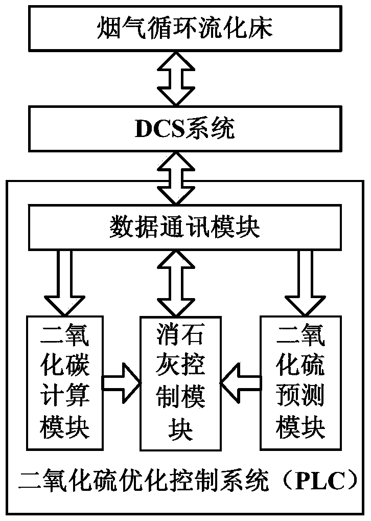
[0042] figure 1 It is a schematic diagram of an optimal control method for flue gas circulating fluidized bed desulfurization. The DCS system is respectively connected to the flue gas circulating fluidized bed and the sulfur dioxide optimization control system based on PLC. The optimization system includes: data communication module, sulfur dioxide prediction module, carbon dioxide calculation module and slaked lime control module. Among them, the data communication module exchanges data with the DCS system, the sulfur dioxide prediction module and the carbon dioxide calculation module are respectively connected to the data communication module and the slaked lime control module, and the slaked lime control module is connected to the ...


PUM


Abstract

The invention discloses an optimization control method for flue gas circulating fluidized bed desulfurization, which belongs to the technical field of desulfurization of thermal power units. The DCS system is respectively connected to the flue gas circulating fluidized bed and a PLC-based sulfur dioxide optimization control system. The system consists of a sulfur dioxide prediction module and a carbon dioxide calculation module respectively connected to the data communication module and the slaked lime control module, and the slaked lime control module is connected to the data communication module; the data communication module and the DCS system exchange data with each other. The present invention can adjust the feeding amount of slaked lime in a timely, dynamic and accurate manner through the SO2 prediction model and the calculation of the CO2 amount of the flue gas at the inlet of the desulfurization tower, and fundamentally avoids the excessive discharge of SO2 and the waste of resources such as slaked lime, etc. It reduces CO2 emissions to a certain extent, and has high reference significance in engineering.

Description

technical field [0001] The invention belongs to the technical field of desulfurization of thermal power units, and in particular relates to an optimal control method for flue gas circulating fluidized bed desulfurization. Background technique [0002] Circulating fluidized bed flue gas desulfurization technology is a new type of desulfurization process developed in the 1980s. It originated from the roasting process of cement and metallurgy. It is based on a circulating fluidized bed, through multiple cycles of the absorbent, prolongs the contact time between the absorbent and the flue gas, greatly improves the utilization rate of the absorbent, and can approach or reach the wet process at a lower calcium-sulfur ratio desulfurization efficiency. Circulating fluidized bed dry desulfurization technology has a simple system and relatively low speculation, which has gradually attracted the attention of more and more countries. This technology is a flue gas with the largest singl...

Claims


Application Information

Patent Timeline
Patent Type & Authority Patents(China)
IPC IPC(8): G05B19/418
CPCY02P90/02
Inventor 张文广张越刘吉臻曾德良杨婷婷高明明房方牛玉广
Owner NORTH CHINA ELECTRIC POWER UNIV (BAODING)
Why Eureka
Try Eureka