Blow-by gas delivery path abnormality detection device for internal combustion engine

An anomaly detection, internal combustion engine technology, applied in the direction of engine measurement devices, internal combustion piston engines, combustion engines, etc., can solve problems such as inability to release blowby gas

Active Publication Date: 2020-12-01
TOYOTA JIDOSHA KK
View PDF27 Cites 0 Cited by
  • Summary
  • Abstract
  • Description
  • Claims
  • Application Information

AI Technical Summary

Problems solved by technology

In addition, the blow-by gas contains a large amount of unb...

Method used


Image

  • Blow-by gas delivery path abnormality detection device for internal combustion engine
  • Blow-by gas delivery path abnormality detection device for internal combustion engine
  • Blow-by gas delivery path abnormality detection device for internal combustion engine

Examples


Embodiment Construction

[0065]

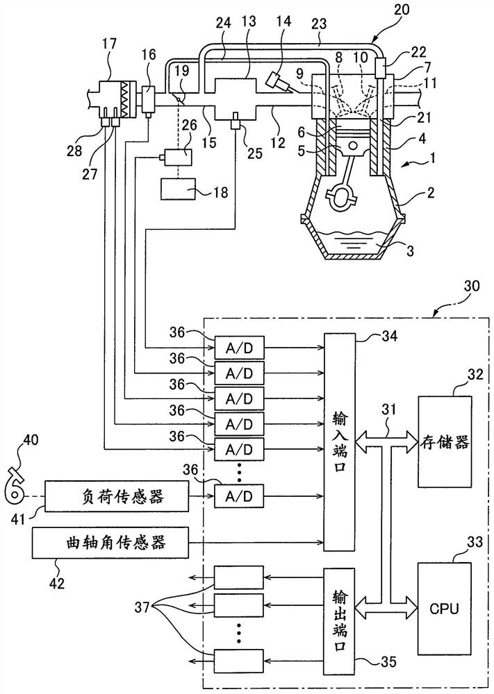
[0066] figure 1 An overall view of the blow-by gas delivery path abnormality detection device is shown. refer to figure 1 , 1 represents the body of the internal combustion engine, 2 represents the crankcase, 3 represents the lubricating oil retained in the crankcase 2, 4 represents the cylinder block, 5 represents the piston, 6 represents the combustion chamber, 7 represents the cylinder head, 8 represents the intake valve, 9 represents Intake port (intake port), 10 represents an exhaust valve, and 11 represents an exhaust port (exhaust). The intake port 9 is connected to a surge tank 13 common to all the cylinders via an intake branch pipe 12 , and a fuel injection valve 14 is disposed on each intake branch pipe 12 . The surge tank 13 is connected to an air cleaner 17 via an intake duct 15 and an intake air amount detector 16 . A throttle valve 19 driven by an actuator 18 is arranged in the intake line 15 .

[0067] On the other hand, if figure 1 As shown, the ...


PUM


Abstract

The invention provides a blow-by gas delivery path abnormality detection device for an internal combustion engine, which can accurately detect blow-by gas leakage abnormality. A learning completion neural network in which an engine load, an engine rotational speed, and an intake air pressure in an engine intake passage downstream of a throttle valve (19) are stored as input parameters of the neural network, and weight learning is performed as a truth value tag when blow-by gas leaks from a blow-by gas delivery passage (20). When the vehicle is running, the learned neural network is used to detect a leak abnormality of blow-by gas from the blow-by gas delivery path (20) on the basis of the input parameter.

Description

technical field [0001] The invention relates to an abnormality detection device for a blow-by gas delivery path of an internal combustion engine. Background technique [0002] In an internal combustion engine, a part of the combustion gas in the combustion chamber leaks into the crankcase through gaps between piston rings, and the gas leaked into the crankcase, that is, blow-by gas, stays in the crankcase. The blow-by gas contains highly acidic water, which causes deterioration of the engine oil and generation of rust inside the engine. Therefore, it is necessary to ventilate the inside of the crankcase so that the blow-by gas does not remain in the crankcase. . In addition, since a large amount of unburned gas is contained in the blow-by gas, the blow-by gas cannot be released to the atmosphere. Therefore, generally, the internal combustion engine has a blow-by gas exchange device, and the blow-by gas exchange device sends the blow-by gas in the crankcase of the internal ...

Claims


Application Information

Patent Timeline
IPC IPC(8): F01M13/00
CPCF01M13/00F01M13/0011F01M2250/00F01M2250/62F01M2250/64F02M35/10222F02D41/22F02D41/1405F02D2250/08F02D2200/0408F02D2200/0406F02D2200/101F02D2200/703F02D2200/1002Y02T10/40F01M2013/0083F01M2250/66F01M2013/0094F01M13/023F01M2013/0088
Inventor 武藤晴文大久保直也片山章弘桥本洋介
Owner TOYOTA JIDOSHA KK
Why Eureka
Try Eureka