Co-location differential speed reducer

A technology of differential reduction and reducer, which is applied in the direction of differential transmission, transmission, belt/chain/gear, etc. It can solve the problems of inconvenient manufacturing and maintenance of gears, hindering performance, complex structure of planetary reducer, etc., and achieve The effect of enriching the transmission ratio selection

Inactive Publication Date: 2020-12-01
周承岗
View PDF6 Cites 2 Cited by
  • Summary
  • Abstract
  • Description
  • Claims
  • Application Information

AI Technical Summary

Problems solved by technology

The existing coaxial reducer technology types mainly include planetary, pinwheel cycloid, rotation vector RV and harmonic, and the transmission mode is gear transmission. Among them, as the most widely used type, the reduction ratio of the planetary reducer is determined by The diameter of the transmission subassembly itself, the number of teeth and other geometric parameters are determined by the multiple relationship, and the entire transmission structure is also designed according to the multiple logic. This basic shifting principle has made the planetary reducer, but it has also become a factor hindering its further performance improvement. ——Because of the limited material strength and correct meshing conditions, the geometric parameters of the pinion gear of the transmission pair can easily reach the minimum limit. To obtain a larger transmission ratio, it is necessary to increase the diameter of the large gear, the number of teeth or the number of transmission stages, so that The structure becomes more complex, and the volume, weight and manufacturing cost also increase. More i...

Method used


Image

  • Co-location differential speed reducer
  • Co-location differential speed reducer
  • Co-location differential speed reducer

Examples


Embodiment Construction

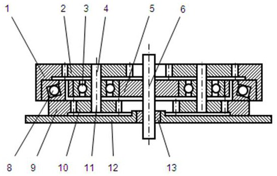
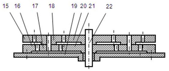
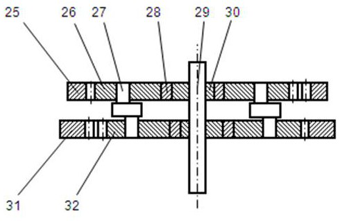
[0027]The transmission wheel of the present invention comprises a co-position differential gear train; a co-position differential gear train of a basic structure has two co-position transmission wheel sets, and the transmission wheels of each other correspond to a co-position group, and the two transmission wheels of one group can be Synchronous rotation, revolution, parallel rotation or simultaneous rotation and revolution, the co-location group is called a synchronous group, and the other group of transmission wheels that are paired with it has coaxial or parallel shafts, one of which is fixedly installed as a stator, and the other rotationally installed as a stator. Rotor, the co-location group is called differential group; the synchronous group and the differential group are directly transmitted or driven through the intermediate wheel; the co-located differential gear train uses the synchronous group as the input element and the rotor as the output element for deceleration ...


PUM


Abstract

The invention discloses a co-location differential speed reducer which is a speed reducer with a co-location differential gear train. A transmission structure of the co-location differential speed reducer is designed by combining differential logics and multiple logics, the reduction ratio is negatively correlated with the difference value of two contrast rotating speeds, and the difference valuecan be infinitely close to zero from the positive direction and the negative direction, so that the reduction ratio can tend to be infinitely great or infinitely small, how large the reduction ratio is is not mainly determined by how large the multiple of geometrical parameters of assemblies of a transmission gear train is and is mainly determined by how approaches the multiple of geometrical parameters of two transmission gear trains is, under the condition that the sizes are equal, a wide output range and a large reduction ratio can be obtained, or under the same reduction ratio, the size issmaller or the load capacity is larger. On the basis, multiple zero-backlash transmission methods are adopted to reduce return difference, and multiple other technical means are matched to obtain more excellent comprehensive performance and a larger application range.

Description

technical field [0001] The invention relates to a reducer, especially a reducer related to extreme technical features such as super large reduction ratio, zero backlash and the like. Background technique [0002] As an indispensable transmission device in the field of power machinery, the reducer has evolved a lot of structural types with the development of the world's industrial civilization for hundreds of years. Today, with the rapid development of aerospace, automation, robotics and other fields, It has ushered in a new round of development opportunities. At the same time, it is also facing higher requirements in terms of transmission ratio, return difference, precision and strength. The existing coaxial reducer technology types mainly include planetary, pinwheel cycloid, rotation vector RV and harmonic, and the transmission mode is gear transmission. Among them, as the most widely used type, the reduction ratio of the planetary reducer is determined by The diameter of ...

Claims


Application Information

Patent Timeline
IPC IPC(8): F16H48/10F16H48/38
CPCF16H48/10F16H48/38
Inventor 周承岗
Owner 周承岗
Why Eureka
Try Eureka