
Internal horizontal damping method applied to optical fiber inertial navigation system

A technology of optical fiber inertial navigation and horizontal damping, which is applied in navigation calculation tools, navigation through speed/acceleration measurement, and measurement devices, etc. It can solve problems that affect the accuracy of the optical fiber inertial navigation system, large oscillation amplitude, and large mean square error

Inactive Publication Date: 2020-12-01
贵州航天控制技术有限公司
View PDF5 Cites 0 Cited by
  • Summary
  • Abstract
  • Description
  • Claims
  • Application Information

AI Technical Summary

Problems solved by technology

However, adding a damping link to the loop will also affect the Shura tuning condition of the loop, so that the system error is affected by the acceleration of the carrier, and the system will produce an error angle proportional to the acceleration of the carrier
Although this error angle only appears in the dynamic process, the error will disappear within one or two Shula cycles with the damping effect, but a Shula cycle is as long as 84.4 minutes, which is very common for the general carrier to maneuver during this period. In fact, the resulting error angle may accumulate over time, which seriously affects the accuracy of the fiber optic inertial navigation system
[0004] In addition, the fiber-optic inertial navigation system is a critically stable system. Under the excitation of constant error sources, the system output errors include Shura period, Foucault period, and earth rotation period. Under the excitation of random error sources, the system errors will slowly accumulate. , and the oscillation amplitude is getting bigger and bigger, the mean square value of the error is also getting bigger and bigger, which reduces the working accuracy of the inertial navigation system

Method used


Image

  • Internal horizontal damping method applied to optical fiber inertial navigation system
  • Internal horizontal damping method applied to optical fiber inertial navigation system
  • Internal horizontal damping method applied to optical fiber inertial navigation system

Examples


Embodiment Construction

[0068] In order to make the technical problems, technical solutions and beneficial effects to be solved by the present invention clearer, the present invention will be further described in detail below in conjunction with the accompanying drawings and embodiments. It should be understood that the specific embodiments described here are only used to explain the present invention, not to limit the present invention.

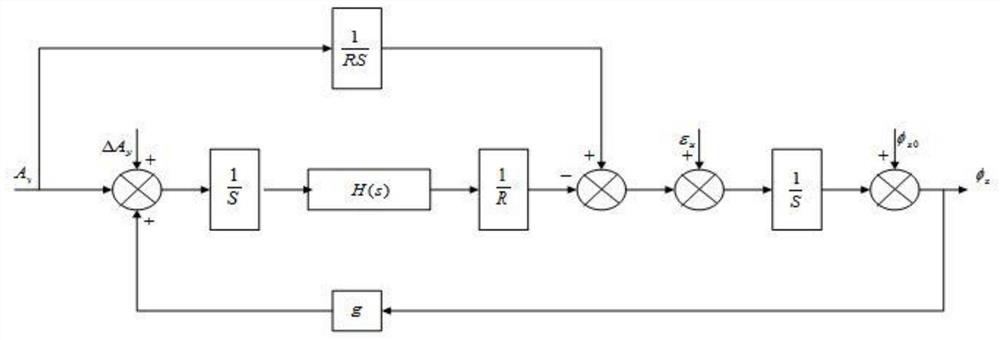
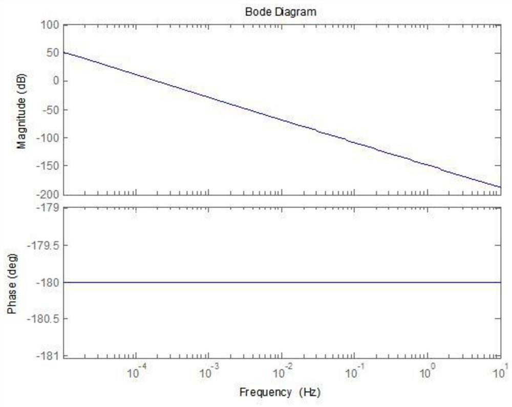
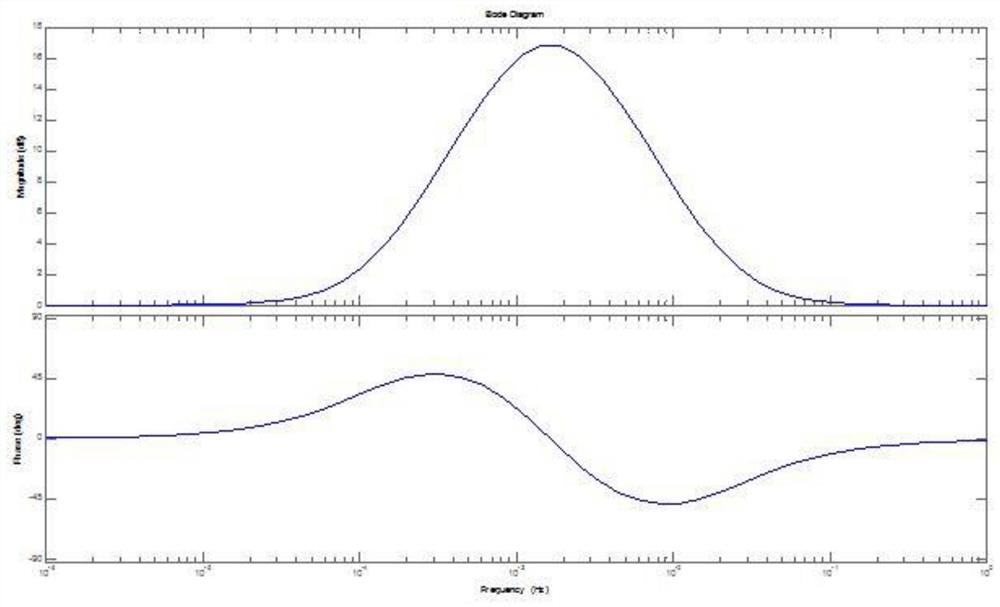
[0069] refer to figure 1 , the present invention provides an internal horizontal damping method applied to the fiber optic inertial navigation system. According to the principle of the fiber optic inertial navigation system, the method establishes a fiber optic inertial navigation horizontal damping network control model, and determines the second-order system cutoff frequency, system bandwidth, and connection frequency. In the section, the horizontal damping correction network is added to the navigation algorithm of the fiber optic inertial navigation system, so t...


PUM


Abstract

The invention discloses an internal horizontal damping method applied to an optical fiber inertial navigation system. According to the method, based on the principle of an optical fiber inertial navigation system, an optical fiber inertial navigation horizontal damping network control model is established, a second-order system cut-off frequency band, a system bandwidth band and a connection frequency band are determined, and a horizontal damping correction network is added into an optical fiber inertial navigation system navigation algorithm such that an optical fiber inertial navigation system has damping characteristics, and Shuler oscillation components output by optical fiber inertial navigation attitudes, speeds and positions are inhibited. On the basis of the optical fiber inertialnavigation horizontal damping network control model, second-order system cut-off frequency, system bandwidth, connection frequency band design and the like are determined; the horizontal damping correction network is added into the navigation algorithm of the optical fiber inertial navigation system such that the inertial navigation system has damping characteristics, inherent error oscillation ina strapdown inertial navigation system is autonomously eliminated, and the precision of the strapdown inertial navigation system is improved.

Description

technical field [0001] The invention relates to an error compensation method of an optical fiber inertial navigation system, in particular to an internal horizontal damping method applied to the optical fiber inertial navigation system. Background technique [0002] According to the principle of the fiber optic inertial navigation system, taking the northbound loop of the system as an example, the horizontal damping network control model of the fiber optic inertial navigation system is established. After the northward accelerometer of the system is sensitive to the specific force of the carrier, the northward acceleration is obtained through the compensation of the harmful acceleration and the error of the accelerometer device, and the northward motion velocity of the carrier is obtained after integration, thereby obtaining the eastward rotational angular rate of the carrier due to the northward motion , and the angular rate sensitive to the gyro is the angular velocity of t...

Claims


Application Information

Patent Timeline
IPC IPC(8): G01C25/00G01C21/16G01C21/20
CPCG01C25/005G01C21/16G01C21/20
Inventor 王文举刘生攀刘杰刘玉玲王晓强
Owner 贵州航天控制技术有限公司
Learn More