Pupil compensation device and photoetching machine

A compensating device and a technology for compensating light, applied in the field of lithography, can solve the problems of simple structure of the pupil compensation device and lithography machine, high coupling efficiency, etc., and achieve high coupling efficiency, high reliability, and simple structure Effect

Active Publication Date: 2020-12-01
SHANGHAI MICRO ELECTRONICS EQUIP (GRP) CO LTD
View PDF7 Cites 0 Cited by
  • Summary
  • Abstract
  • Description
  • Claims
  • Application Information

AI Technical Summary

Problems solved by technology

[0008] The object of the present invention is to provide a pupil compensation device and a lithography machine to solve the pr

Method used


Image

  • Pupil compensation device and photoetching machine
  • Pupil compensation device and photoetching machine
  • Pupil compensation device and photoetching machine

Examples


Example Embodiment

[0050] The pupil compensation device and the lithography machine proposed by the present invention will be further described in detail below with reference to the accompanying drawings and specific embodiments. The advantages and features of the present invention will become more apparent from the following description. It should be noted that the accompanying drawings are all in a very simplified form and in inaccurate scales, and are only used to facilitate and clearly assist the purpose of explaining the embodiments of the present invention.
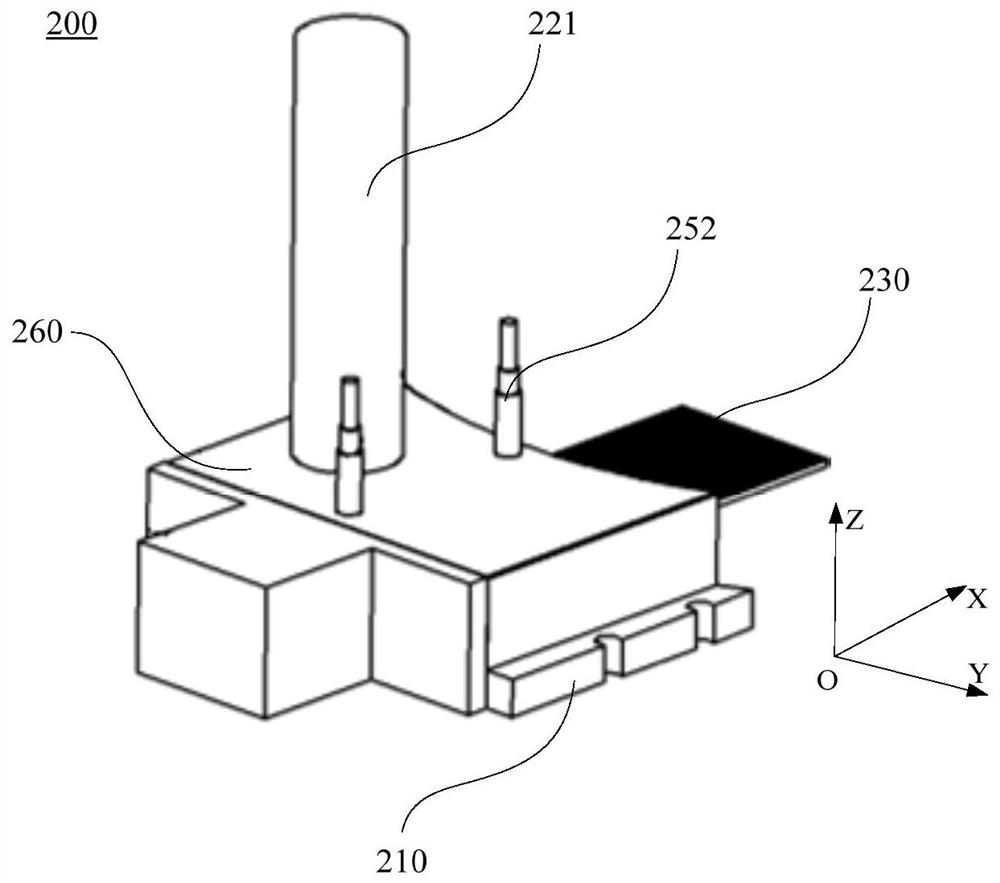
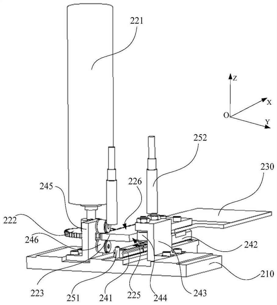
[0051] refer to figure 2 , image 3 and Figure 4 , figure 2 is a schematic structural diagram of a pupil compensation device 200 in an embodiment of the present invention, image 3 Yes figure 2 A schematic diagram of the internal structure of the pupil compensation device 200 after removing the cover 260, Figure 4 Yes figure 2 Another schematic diagram of the internal structure of the pupil compensation device 200 after r...


PUM


Abstract

The invention provides a pupil compensation device and a photoetching machine. The pupil compensation device comprises a bracket main body, a driving device and a compensation mechanism, and the driving device is arranged on the bracket main body; the driving device is used for driving the compensation mechanism to move on a pupil plane, the compensation mechanism is used for compensating pupil uniformity, the compensation mechanism comprises a compensation main body and a compensation piece arranged on the compensation main body, the compensation main body is connected with the support main body in a sliding mode, and the compensation piece is used for compensating pupil uniformity. According to the pupil compensation device, the pupil uniformity can be compensated on the pupil plane, andthe compensation degree of the pupil uniformity by the compensation mechanism is adjustable, so that the position of the compensation mechanism can be adjusted according to different pupil uniformitycompensation requirements, and the coupling efficiency of the pupil compensation device is high. In addition, the pupil compensation device is simple in structure and high in reliability.

Description

technical field [0001] The invention relates to the technical field of photolithography, in particular to a pupil compensation device and a photolithography machine. Background technique [0002] The exposure system in the projection lithography machine transfers the pattern on the mask surface to the silicon wafer surface through the illumination system, and forms the required pattern. The indicators of the illumination system include the spot energy, spot uniformity and pupil uniformity projected onto the mask surface, where the spot energy determines the productivity of the lithography machine, and the pupil uniformity determines the relative difference in the directional width of the exposure lines, namely Indirectly affect the resolution of the lithography machine. [0003] The lighting system mostly includes a mercury lamp and a quartz rod uniform light unit, especially when the exposure field of view of the exposure system is a rectangular structure, the pupil unifor...

Claims


Application Information

Patent Timeline
IPC IPC(8): G03F7/20
CPCG03F7/70091G03F7/70191
Inventor 赵峰
Owner SHANGHAI MICRO ELECTRONICS EQUIP (GRP) CO LTD
Why Eureka
Try Eureka